
Introduction - SPECIAL ACCESSORIES
- Make
- Fiat
- Model
- Stilo Factory Service Manual
- Year
- 2001–2007
- Section
- Special accessories › Introduction - SPECIAL ACCESSORIES
Introduction - SPECIAL ACCESSORIES
OPERATION
The engine managment systems for petrol engines with motorized throttles and diesel engines with electronically controlled injection times include the Cruise Control function, i.e. a system which automatically maintains the cruising speed set by the driver.
The Cruise Control is integrated in the steering column switch unit which also controls the direction indicators and front/rear window wiper.
The figure shows the location of the Cruise Control.
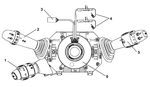
1 - Cruise Control lever
2 - Lights/direction indicators lever
3 - Horn/radio controls cable
4 - Air Bag module connectors
5 - Front/rear wiper control lever
6 - Air Bag clock spring
OPERATION
The third lever on the steering column switch incorporates the Cruise Control commands, namely:
- a ring switch for activating/deactivating the system;
- a ring switch which memorises the car's increase/decrease in speed;
- a Resume button for recalling the memorised speed.
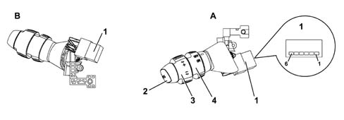
A - Front view of Cruise Control lever
B - Rear view of Cruise Control lever
1 - 6 pin connector
2 - Resume button for recalling speed memorized
3 - Ring switch with increase/decrease memorizing function (acceleration position: +; deceleration position: -)
4 - Ring switch (ON: Cruise activated; OFF: Cruise deactivated)
OPERATION
Six-way connector pin out
| Pin | Function |
|---|---|
| 1 | Resume command positive signal |
| 2 | INT from F-35 CPL |
| 3 | Headway signal for selecting safety distance from obstacle |
| 4 | Cruise control engagement positive signal (on) |
| 5 | Deceleration positive signal (-) |
| 6 | Acceleration positive signal (+) |
The electronic system is managed by the injection unit (NCM) ME7.3.1. It automatically maintains the cruising speed set by the user and actuates this control via a command on the motorised butterfly. - The Cruise Control system may be present on both cars with manual gearbox and cars with automatic transmission connected to the engine control on CAN network.
MEMORISATION OF THE PRESELECTED SPEED
To activate the Cruise Control function, it is necessary to:
- 1 - activate the bistable ring switch in the ON position;
- 2 - bring the car up to the desired speed; remember that the Cruise Control can only be activated for speeds of over 30 km/h. It is advisable to switch it on in fourth gear or upwards, and on road conditions which allow the set speed to be maintained safely.
- 3 - operate the ring switch towards the (+) mark: this is switch with automatic return.
- 4 - release the accelerator pedal and allow the system to act directly;
- 5 - the instrument panel (NQS) will light up the light (LED) fixed in accordance with the signal coming from the fuel injection control unit (NCM), via the CAN network, indicating the Cruise Control operating status. When it goes out, this indicates the deactivation of the system.
VARIATION OF THE MEMORISED SPEED
To change the memorisation of the car speed corresponding to the moment when it was memorised, it is necessary to:
(A) Speed increase:
- operate the ring switch towards the (+) mark: an acceleration ramp is produced at a constant gradient which can be programmed;
- on release of the switch (automatic return of the switch), the system maintains and memorises the new speed reached by the car.
(B) Speed reduction
- operate the ring switch towards the (-) mark: the car speed is reduced in relation to that set previously by the Cruise Control; release the button and the system will maintain the new speed reached by the car.
The Cruise Control can operate within the full range of rpm permitted by the engine, for both versions with automatic transmission on CAN network and versions with manual gearbox.
FUNCTION OF RESUME BUTTON
By pressing the automatic return button located on the top of the Cruise Control lever, this function enables the care to be brought to the last speed value memorised, if the Cruise Control has been switched off because of particular conditions (e.g. operation of the cluth or use of the stop switch during braking).
In the case of manual gearbox, the same gear used when the speed is sest must have been engaged. If a speed value has not been recognised, pressing the button has no effect.
DEACTIVATION OF THE CRUISE CONTROL (BY THE USER/SUBSYSTEMS)
(A) The Cruise Control is deactivated by the user by:
- turning the ring switch to the OFF position
- switching off the engine;
- operating the brake or clutch pedal (in these cases the last speed reached remains memorised, and can be recalled by pressing the Resume button).
- vehicle speed below the permitted minimum (about 30 km/h) or above the permitted maximum;
- setting the automatic transmission selector lever to position P, N, R (on robotised gearbox the information is on the CAN network); on manual gearboxes, if the lever is operated without using the clutch, the rpm and car speed will not be consistent; in all these cases, pressing the Resume button re-activates the system.
- operating the accelerator with Cruise Control active: by pressing the accelerator (e.g. for overtaking) the Cruise Control permits a temporary increase in the car speed because it is temporarily deactivated, but as soon as the action on the accelerator pedal ceases, the system reactivates the memorised speed setting.
The recognition of the engaged gear with car moving for automatic transmission is available on the CAN network; for the manual gearbox, the engaged gear is recognised by comparing the car speed with the engine rpm with clutch engaged.
For safety reasons, the ASR (Antislip Regulation) and VDC (Vehicle Dynamic Control) functions have priority over the Cruise Control; when the operation of the ASR/VDC is over, the Cruise Control is automatically reactivated at the last speed value memorised.
(B) The Cruise Control is automatically deactivated if:
- acceleration higher than the set limit occurs (e.g. a rapid descent);
- deceleration higher than the sest limit occurs: the gear selector lever is used without the clutch.
However, the system switches off automatically when the signals used by the Cruise software are incorrect because they are attributable to faults in the components;
- vehicle speed sensor;
- accelerator pedal potentiometer;
- plausibility of brake/stop lights switches;
- plausibility of clutch switch;
- lever position on automatic transmissions;
- plausibility of Cruise switch and Resume button;
- plausibility of Cruise switch and (+) (-) buttons;
The Cruise Control system is also deactivated in all cases where errors occur on components which impair engine operation, such as:
- engine management control unit;
- engine rpm sensor;
- electronic throttle body actuators/sensors (petrol engines);
- engine load meter (petrol engines);
- coils (petrol engines);
- fuel injectors;
- high-pressure system components (diesel engines);
- turbo actuators/sensors (if present).
A 'fault' is a serious malfunction of the engine control system or Cruise Control system, such as to require that the Cruise Control become 'blocked' (i.e. disabled until the engine is turned off). An 'anomaly' is an anomalous condition (due to a malfunction or incorrect command from the user, such as, for example, involuntary simultaneous activation of the Resume buttons and (+) (-) ring buttons, such as to require that the Cruise Control be deactivated, but not blocked. In both cases of fault and anomaly, an error code which can be read by a diagnostic instrument must be memorised. Cruise Control errors must not cause the fuel injection control unit (ECN) warning light to come on, or the Cruise Control warning light.
Specifications
The ACC (Adaptive Cruise Control) assists the driver in controlling both the cruising speed and the distance from the vehicle in front and allows the vehicle to be driven at the desired speed without pressing the accelerator pedal.
The system makes it possible to reduce driver fatigue on motorways, particularly on long trips, because the set speed is maintained automatically and this helps towards keeping a correct distance from the vehicle in front. Driving at a constant speed also makes it possible to restrict fuel consumption and improves the traffic flow.
The electronically controlled system operates independently and does not require communication between vehicles or the need for other vehicles to be equipped with a similar system.
The speed regulator is not an 'automatic pilot', but a system that helps the driver leaving them full responsibility for manoeuvres carried out whilst driving in traffic and for respecting the highway code and other traffic regulations.
The Adaptive Cruise Control is not an anti-crash system: it is not capable of detecting and signalling obstacles in the driving path nor of stopping the vehicle if obstacles are present. Each time the driver operates the brake, clutch or accelerator the speed control system is informed and the responsibility for road safety always lies with the driver of the vehicle.
The maximum deceleration automatically implemented by the system of 2.5 m/s[sup2 ] is limited in relation to the actual capacity of the braking system which means that the only driver can carry out emergency braking when needed.
The speed governor should only be activated when traffic and route conditions allow, i.e. when a constant speed can be safely maintained for a sufficiently long stretch.
The system can only be switched on when the speed of the vehicle is between 30 and 160 km/h and is switched off automatically when the brake pedal is pressed. If the speed goes below 30 km/h or above 160 km/h when the system is switched on, a buzzer warns the driver until they regain control of the vehicle's speed.
The advantage of this system are:
- improved driving comfort: it takes the burden of adjusting the speed to suit traffic conditions away from the driver
- more economical: it allows peaceful driving and reduces consumption
- improved efficiency: it improves the traffic flow thanks to the automatic speed control
composition
The system components are:
- radar sensor (NAC: Adaptive Cruise Control Node),
- Cruise Control lever
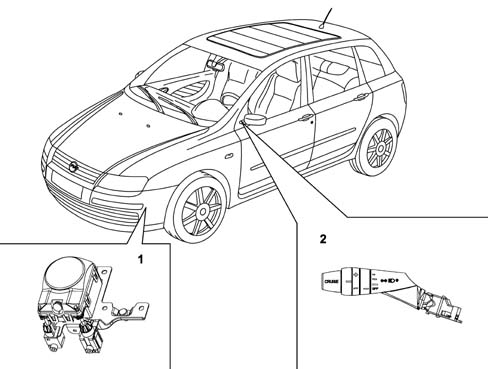
1 - Radar sensor
2 - Cruise Control lever
operation
The system can be seen as an extension of the traditional Cruise Control system, not only capable of maintaining a set speed, but also of adapating the speed of the vehicle to suit the road traffic conditions by accelerating and decelerating (including using the brakes).
The system is not activated when the gear lever is in the manual position and with the engine switched off
Traditional Cruise Control
Only limited manual acceleration and deceleration operations are permitted after the desired speed has been set by the driver.
Adaptive Cruise Control
If no vehicle is identified in the driving path then the system maintains the speed that has been set; if, on the other hand, a vehicle is detected in the driving path, then the system automatically maintains the correct distance from the vehicle in front.
The function is disabled each time the brake pedal is operated whilst pressing the accelerator pedal allows the speed set to be exceeded without disabling the function.
The driver receives a summary of the speed set data, presence/absence of an obstacle and tracking via a simple display in the dashboard.
Driver input
The driver can make use of 4 controls to manage the system as well as using the brake to release it and the accelerator to override it:
- ON/OFF,
- SET + (speed increase)
- SET - (speed decrease)
- RESUME
In addition to these controls also found on the traditional Cruise Control system, there is the HEADWAY or distance which, depending on the speed of the vehicle, must be maintained between two vehicles
The lever on the steering column switch unit is used to input data.
When the ignition key is turned to the OFF position or the ring nut is turned to the OFF position, the speed saved is cancelled and the system deactivated.
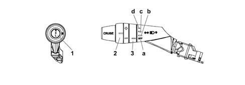
1 - Resume button
2 - Speed setting ring nut (SET)
3 - Cruise Control/Headway settings on ring nut
a - Cruise Control OFF position
b - Long distance Headway position
c - Medium distance Headway position
d - Short distance Headway position
Driver input
The instrument panel display provides the driver with a summary of the information relating to the speed stored, whether or not there is a vehicle and the distance set.
ON/OFF
The driver activates the system by turning the ring nut (3) into any Headway position.
When the function is activated the icon illustrated is displayed in the control panel. This icon remains on until the system is switched off.
When the ACC system is activated, the warning 'adaptive cruise control on' plus the symbol are displayed. This screen remains for 5 secs. after which the screen plus the 'ACC symbol appear in the top left corner.
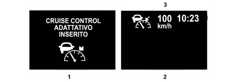
1 - Screen displayed as the ACC system is switched on
2 - Screen normally activated with the system on
3 - Speed set
ON/OFF
The driver can switch the system off by turning the ring nut (3) to the OFF position.
When the system is switched off all the information in the control panel for the function disappears.
SET
After the ACC system is switched on the desired speed can be set using the SET control. The vehicle's current speed is considered to be the reference speed (cruising speed). This speed can automatically decrease depending on the traffic conditions and the system moves from a speed control state to a distance control state. The display in the instrument panel informs the driver of the system's operating state. The minimum speed that can be set is 30 km/h, the maximum 160 km/h.
If the ring nut is turned the speed stored varies continuously in intervals of around 10 km/h. The new speed is automatically maintained.
The moment the driver presses the SET control, the speed set is displayed on the control panel (speed control state).
SPEED INCREASE: the speed can be increased in 10 km/h steps using the increase control (SET +) The new speed set is shown on the display and replaces the previous one.
SPEED DECREASE: the speed can be decreased in 10 km/h steps using the decrease control (SET -). The speed can also be decreased through the intervention of the braking system, with a maximum deceleration of 2.5 m/s[sup2 ]. The new speed set is shown on the display and replaces the previous one.
RESUME
Whilst driving with the Adaptive Cruise Control activated the driver can disable the system by operating the braking system. In this case the cruising speed set previously is stored in the memory and can be reactivated by pressing the RESUME button.
The driver is aware of the Resume state through the flashing of the set speed in the display and the need to restore the function.
If the system was in the DISTANCE CONTROL state before the system was disengaged, the presence of the obstacle in front remains.
HEADWAY
The ring nut (3) makes it possible to set the distance that, depending on the speed, should be maintained between the vehicle and the vehicle in front when the distance control is activated.
For convenience the distance is expressed in seconds and represents the time required to cover the distance that separates the vehicle from the one in front.
There are three distance setttings:
- far corresponding to about 2 seconds;
- standard corresponding to about 1.5 seconds;
- overtake corresponding to about 1 second.
Logically, as distance is a function of speed, the distance between two vehicles increases gradually as the speed increases, even if the distance setting is kept constant.
The headway set is shown in the control panel through the DISTANCE CONTROL state icon.
The information coming from the outside temperature sensor is used in calculating the safe distance.
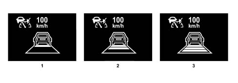
1 - FAR setting
2 - STANDARD setting
3 - OVERTAKE setting
Override (accelerator)
The system can be momentarily by-passed by pressing the accelerator pedal; as soon as you take your foot off the pedal the system returns to the cruising speed set previously.
The driver is warned of the OVERRIDE state by the set speed flashing in the display.
During this state the icon of an obstacle identified in the driving path, if fitted, remains activated whilst the distance control information, if present, is disactivated.
Release (braking)
The system is disabled if the driver operates the brake pedal or the handbrake.
Memorizing the speed
To memorize the speed, turn the ring nut (3) to one of the Headway positions or bring the vehicle to the desired speed.
Turn the ring nut (2) to SET + for at least three seconds, then release it. The vehicle speed is stored in the memory and shown on the instrument panel display; the accelerator pedal can now be released.
The vehicle will continue driving at the constant speed memorized until one of the following conditions occurs:
- the brake pedal is pressed;
- the clutch pedal is pressed.
If necessary (e.g. for overtaking) it is possible to simply accelerate by pressing the accelerator pedal; afterwards, when the accelerator pedal is released the vehicle will resume the speed memorized previously.
Resuming the speed memorized
If the system has been deactivated by pressing the brake pedal or the clutch pedal, the speed memorized can be restored in the following way:
- accelerating gradually until the speed is close to the one memorized;
- on versions with a manual gearbox, by engaging the gear selected at the tim the speed was memorized (4th or 5th speed);
- by pressing the RESUME button.
The speed memorized flashes in the display to warn the driver of the resume condition.
Increasing the speed memorized
There are two ways of increasing the speed memorized:
- by pressing the accelerator and then memorizing the new speed (turning the ring nut (2) for more than three seconds);
- momentarily turning the ring nut (2) to the SET + position: an increase in the speed of around 10 km/h corresponds to each ring nut impluse, whilst pressing it constantly produces a corresponding continuous increase in speed with 10 km/h intervals approx. If the ring nut B is released, the new speed will automatically remain stored in the memory.
The new speed set will be shown in the display replacing the previous one.
Decreasing the speed memorized
There are two ways of decreasing the speed memorized:
- by switching off the device (e.g. pressing the brake pedal) and then memorizing the new speed (turning the ring nut (2) to the SET + position for at least three seconds);
- by keeping the ring nut (2) in the SET - position until the new speed is reached and automatically remains stored in the memory.
The new speed set will be shown in the display replacing the previous one.
Zeroing the speed memorized
The speed memorized will automatically be zeroed:
- by turning the engine off;
- by moving the switch A to the OFF position.
When the system is deactivated all the information in the instrument panel display will be cancelled.
Maintaining the speed and distance
The system maintains the speed memorized when no vehicle is identified in the driving path. If, on the other hand, a vehicle is identified, the system automatically implements several interventions (acceleration, deceleration or gentle braking) to maintain the set distance from the vehicle in front.
The maximum deceleration that can automatically be implemented by the system is limited in relation to the actual capacity of the vehicle's braking system and therefore only the driver is capable of carrying out emergency braking. In this case a buzzer warns the driver of the onset of a dangerous situation.
The system is deactivated each time the brake pedal is operated.
If the accelerator pedal is operated, for example for overtaking, the system is not deactivated and when the accelerator is released the vehicle gradually returns to the speed memorized.
Detecting an obstacle with the system ON but not SET
With the system switched on (ring nut 3 turned to a headway position) but not activated (ring nut 2 not turned yet), the presence of an obstacle is not displayed until the driver gives the SET command.
Only after the driver has set the speed control at least once will the obstacle in front be indicated even in the RESUME and OVERRIDE states until the system is switched OFF
Detecting a vehicle with the system on
When the system is switched on and the ring nut (2) is turned to the SET + position, if there is a vehicle in front (within 150 metres) in the driving path then this is signalled to the driver in the instrument panel display through the following symbol:
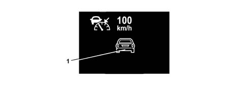
1 - Presence of obstacle indication
Detecting a vehicle with the system on
The symbol shown indicates that the speed and distance control is on with a vehicle detected in the driving path; the vehicle has not yet been 'tracked' by the system because it is either beyond the safe distance or travelling at a higher speed than that memorized.
If, on the other hand, the vehicle is within the safe distance or close to it and the system is in the 'tracking' state, one of the symbols will appear on the display (depending on the distance setting) indicating the activation of the distance control (see HEADWAY setting).
Switching the system off automatically
The system is switched off automatically if the brake pedal is pressed; the symbol for the distance control, if present in the instrument panel display, remains visible and continues to signal the presence of a vehicle in the driving path.
If the system is momentarily deactivated by pressing the accelerator pedal, the speed memorized flashes in the instrument panel whilst the distance control symbol, if present in the instrument panel display, disappears. If the symbol representing a vehicle identified in the driving path is present, it remains visible.
The ACC system is automatically deactivated if the vehicle stability systems (ABS, ASR, MSR, ESP) intervene as follows:
- if the ACC is causing the vehicle to accelerate: it is deactivated immediately,
- if the ACC is causing the vehicle to brake: it is deactivated at the end of the braking manoeuvre.
In both cases the function is restored by pressing the RES button or setting a new speed.
Braking power limits
If the braking power enabled for the function is not sufficient in a particularly critical situation, an alarm (beeper) warns the driver, in good time, of the need to intervene. As soon as the driver intervenes the system moves on from the SET state, the obstacle identified in the driving path symbol remains activated and the distance control state is not displayed.

Function lower operating range limits (30 km/h)
When the speed of the vehicle goes below 30 km/h in the speed control state, the system gives the driver an auditory warning advising them to take control of the vehicle and moves to the SET state; above 30 km/h the driver can set the desired speed once again using the SET button. The ACC ON state only remains on the control panel display. If there is an obstacle in the driving path, the driver is given this information.

Function lower operating range limits (30 km/h)
The cruise control system is not effective when driving in a traffic queue; starting the vehicle after stopping in traffic is always left to the driver who must also switch the speed control function back on every time using the SET control.
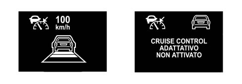
Function lower operating range limits (30 km/h)
The distance control information in the control panel remains unchaged, down to vehicle speeds of 10 km/h, after which the only information available to the driver is that of the presence of an obstacle.
If, on the other hand, the braking power enabled does not guarantee the tracking of the vehicle in front, the system gives the driver an auditory warning advising them to take control of the vehicle and moves to the SET state when the driver brakes. The strategy adopted in the case of braking power limits is applied at this point.

Function upper operating range limits (160 km/h)
When the speed of the vehicle goes above 160 km/h (if the driver has used the override function), the system gives the driver an auditory warning and moves to the OVERRIDE state. When the driver releases the accelerator pedal and the vehicle returns to the system operating range the Adaptive Cruise Control function is automatically reactivated.
The OVERRIDE state information is displayed in the instrument panel:
- speed set flashing;
- obstacle identified in driving path symbol, if fitted, remains activated;
- distance control information disappears.
GEAR CHANGE SUGGESTION
When the speed control system is on, on versions with manual gearboxes, the instrument panel display shows the gear engaged at the time, whilst the recommended gear, if different from the one engaged, will flash to advise the driver of what they should do.

1 - 'Gear change suggestion' (flashing) if the gearbox is not automatic or robotized
Fault messages
Any system faults are signalled by the special warning light in the instrument panel coming on. The fault signal persists even when the system switch is turned OFF.

Fault messages
The cruise control system is completely deactivated, irrespective of the type of fault. Only if the radar sensor is 'blinded', due to the fouling of the aerial or the area of the bumper covering the aerial is the distance control only disabled whilst the speed control remains activated; the driver is warned by a special message in the display that the lens is dirty.
The NAC does not have its own actuators, when it detects any sort of fault in the components linked to the ACC system (NFR, NYL, steering angle sensor, etc.) it also assumes a failure status for safety reasons. When the fault in the component is repaired the ACC system resumes normal operation.
The ACC system moves to the failure state, disabling itself, even if one of the following sub-systems is not working properly:
- braking system (ESP): ACC disabled, fault signal
- lateral acceleration yaw sensor: ACC disabled, fault signal,
- Engine Management Node: ACC disabled, fault signal,
- Automatic Transmission Node: ACC disabled, fault signal,
- C-Can: ACC disabled, fault signal
- Front wheel ABS sensors: recovery operation, no fault signal
- Rear wheel ABS sensors: recovery operation, no fault signal
- Lateral acceleration sensor: recovery operation, no fault signal
Do not place the gear lever in neutral whilst driving with the cruise control system on. It is advisable to only switch the cruise control system on when the traffic and road conditions allow this to be done in complete safety, i.e.: on straight, flat roads,dual carriage ways or motorways, moving traffic and roads with smooth, asphalt surfaces. Do not switch the device on in town or in heavy traffic.
The cruise control system can only be switched on when the speed of the vehicle is between 30 and 160 km/h and, on versions with a manual gearbox, only in 4th or 5th gear depending on the speed of the vehicle. When driving downhill with the device switched on the speed of the vehicle may increase slightly compared with the speed memorized as a result of the change in the engine load conditions.
If the system is not working properly or not working at all, move the switch A to the OFF position and seek assistance from the Lancia Dealer Network after having checked the protective fuse. The switch A can be constantly left in the ON position without damaging the device. It is advisable to deactivate the system when it is not in use by moving the switch A to the OFF position to prevent speeds from being memorized accidentally.
Accelerating round bends
When driving round a bend as soon as the lateral acceleration sensor reaches the pre-set level for maintaining safe driving conditions, he ACC locks the vehicle speed and does not allow further acceleration whilst taking the bend.
Under these circumstances, the speed is not automatically decreased by the ACC system; the control of the speed remains the driver's responsibility.
Behaviour at low temperatures
When the outside temperature goes below 3°C (measured by the outside temperature sensor) the system automatically sets the headway at FAR irrespective of the selection made; when the temperature goes above 5°C the system can be reconfigured by the user.
Behaviour during overtaking
When overtaking a tracked vehicle that is driving at a speed below the one set, the ACC system reduces the distance from the actual vehicle (compared with the set distance) and accelerates briskly during the overtaking manoeuvre.
Operation from the system's standpoint
The various ACC system components converse with one another via the C-Can.
The Engine Management Node carries out the following functions:
- acquires the commands from the cruise control lever on the steering column switch unit directly (Cruise Control ON/OFF, SET +, SET -, Resume)
- acquires the signals for the accelerator pedal position, brake pedal pressed information directly
- acquires the actual vehicle speed signal (and checks it plausibility) and failure signal via the C-Can.
- controls the parameters for the operation of the engine.
The Adaptive Cruise Control Node (NAC) carries out the following functions:
- acquires the headway commands directly,
- acquires the 'outside temperature sensor' and 'left/right direction indicators' information from the C-Can,
- acquires the actual vehicle speed and failure signal at the C-Can.
- manages the operation of the Adaptive Cruise Control.
- transmits the information to be displayed on the instrument panel via the C-Can
- transmits the engine torque request via the C-Can,
- transmits the deceleration request via the C-Can,
- transmits the possible gear change request via the C-Can (directly to the NCA for vehicles with automatic transmission, to the NQS (via the NBC) to display the gear change request in the instrument panel),
- transmits information relating to the following via the C-Can: presence of obstacles, obstacle tracked, failure state, headway setting, operating range limits (below 30 km/h and above 160 km/h), braking power limits in case of the need of the driver to intervene.
The Automatic Transmission Node (NCA) carries out the following functions:
- acquires the actual vehicle speed and failure signals via the C-Can.
- acquires the gear chage requests from the NAC and implements the appropriate strategies.
The NPB carries out the following functions:
- acquires the actual vehicle speed and failure signals at the C-Can
The NFR carries out the following functions:
- acquires the wheel speed signal from the sensors in the drive wheels
- acquires the actual circumference of the wheels for that version from the C-Can
- acquires the signal from the slewing, lateral acceleration and steering angle sensors
- calculates the actual vehicle speed and failure and transmits them via the C-Can
- transmits the actual vehicle speed NBC signal discretely (not via the CAN)
The NBC peforms the following functions:
- acquires the vehicle speed signal from the NFR directly
- carries out the Gateway function between the C-Can and B-Can networks for the following signals: actual vehicle speed, failure from C-Can and information to be shown in the Control Panel display
- transmits the actual circumference of the wheels for that version via the C-Can
The NQS carries out the following functions:
- acquires the actual vehicle speed and failure signals from the B-Can
- manages the speedometer reading
- acquires the Adaptive Cruise Control information from the B-Can
- displays the Adaptive Cruise Control information.
- manages the buzzer
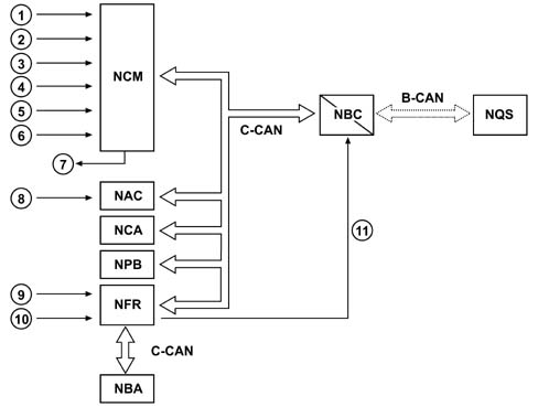
1 - On/off switch
2 - SET +
3 - SET -
4 - RESUME
5 - Accelerator pedal position
6 - Brake pedal switch
7 - Engine management
8 - Headway selection
9 - Wheel rpm sensors
10 - Slewing/lateral acceleration/steering angle sensor
11 - Vehicle speed signal
Operation from the system's standpoint
NAC Pin Out
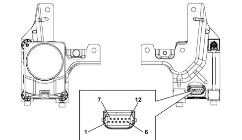
Operation from the system's standpoint
| PIN | FUNCTION |
|---|---|
| 1 | Earth |
| 2 | C-Can H |
| 3 | CAN Low Output |
| 4 | C-Can L |
| 5 | n.c. |
| 6 | Programming Pin for RPU (sets controller into bootstrap mode) |
| 7 | n.c. |
| 8 | CAN High Output |
| 9 | Analogue signal for selecting distance from obstacle (headway, Time Gap) |
| 10 | n.c. |
| 11. | Diagnostic line K |
| 12. | INT from F-35 CPL |
INTRODUCTION
The car is fitted with an electronically-controlled passive safety system which, in the case of a front-end or side crash, partly or completely activates the safety devices depending on the severity of the impact.
The front protection system known as the SMART 2 because it is capable of automatically adapting the activation parameters depending on the seriousness of the accident, whether or not seat belts are worn and the weight of the passenger.
The components of the Air Bag system have been designed to work on a specific car. They therefore may NOT be tampered with, adapted or installed on other types of vehicles.
The Air Bag system components are connected electrically by wiring, integrated in the dashboard wiring loom for the front devices, and in the rear wiring loom for the side devices.
The control unit is connected to the system by means of two connectors, one for the front cable and one for the rear cable.
The passenger's front Air Bag module can be deactivated voluntarily, by a specific key switch located beside the dashboard. The deactivation of the passenger's front Air Bag module does not disable the side Air Bag modules. Thus in the event of a side impact, protection is also offered to any child who may be travelling in the front seat.
The rear Side Bag modules can be voluntarily deactivated by a special switch located under the rear parcel shelf brackets.
The vehicle should be handed over to the customer with the passenger Air Bag deactivtion switch in the ON position and the warning light in the instrument panel off. The rear Side Bag deactivation switch should be in the OFF position and the warning light in the instrument panel on.
For safety reasons continuity checks on the wiring are NOT permitted. To consult the electrical diagram of the system's connections See E7030 AIRBAG.
GRAVE DANGER! If a child seat is fitted on the front passenger seat, the front Air Bag module MUST be deactivated.
COMPOSITION
The system comprises the following devices in four different configurations:
- the basic configuration supplied as standard provides an electronic control unit, two front driver and passenger airbags with dual activation stages, a decentralised supplementary sensor for detecting impact and a manual passenger airbag disablement switch. front seats belts with pretensioners and load limiters are also available.
- in intermediate configuration including front passenger airbags, pretensioners on front seats and also two sidebags on the front seats and two seat belt fastened sensors for the front seats,
- a more comprehensive configuration with front passenger airbags, pretensioners on the front seats and front seat sidebags; and also two side protection Head Bag modules
- the more comprehensive configuration further increases rear safety with two additional Side Bags with pretensioner and load limiter, two supplementary side bagsfor the rear seats which can be deactivated by a special manual switch. An occupant classification sensor fitted on the front passenger seat is only available on thi configuration.
Only the most comprehensive configuration is shown because the control unit is the same for all configurations. certain configurations are not connected in less comprehensive specifications.
To indicate the state of efficiency, the system has:
- fault warning light (red) on the instrument panel;
- passenger Air Bag disabled warning light in the instrument panel;
- rear seat Side Bag disabled warning light in the instrument panel;
- diagnostic socket which converses through the K LINE to check operation via the EXAMINER.
ELECTRONIC CONTROL UNIT
The following figure shows the control unit.
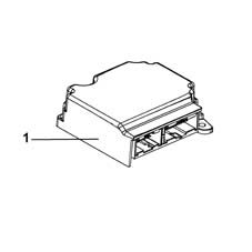
1 - Electronic control unit
ELECTRONIC CONTROL UNIT
The control unit represents the heart of the occupant protection system and is located on the front tunnel under the distributor blower unit and is secured firmly to the bodyshell. It manages all the system detection and activation devices, processing the signals which come from the various sensors inside it and from those around the vehicle.
The control unit must always be fitted with the arrow stamped on the adhesive plate facing the vehicle's direction of travel. Always check that there are no foreign bodies between the control unit and the bodyshell, tightening the bolts to the recommended torque.
COMPOSITION
The control unit contains two longitudinal deceleration sensors, one electronic and the other a mechanical safety sensor which has the function of giving enablement for the activation of the front protection systems, working independently from the electronic sensor. In addition, a third transverse/two-way accelerometric sensor housed inside, provides the go ahead for the activation of the side protection systems, from the satellite sensors fitted in the centre pillars.
If the car's deceleration value, measured by the electronic sensor and processed by the processor in terms of severity of the crash, exceeds the severity level established for the command to activate the devices, the control unit makes sure that this command can only be sent if, at the same time, the safety sensor is closed.
To ensure the correct management of the system, the following functions are present:
- energy accumulation: the control unit receives a 12V supply with the key in the Key On position and from a condenser which acts as an energy reserve ensuring that the front Air Bags work efficienctly even if the supply from the electrical system fails for a few fractions of a second.
- check of earth attachment: the control unit's control logic checks the electrical contact between the bodywork and the control unit;
- fault memory: with the ignition on, the control unit continuously checks that the circuit is working (including the energy reserve circuit), during normal operation of the car and during normal operation of the car and during any crashes, and tests all the electrical parts of the system, indicating the presence of faults by switching on the Air Bag fault warning light on the instrument panel and memorising the fault code.
- crash memory: this records the information, relating to crash events, which have led to the activation of the pretensioners and modules, front or side.
In view of the importance of its functions, the control unit is designed in such a way that it cannot be opened with leaving visible signs of having been tampered with.
If the control unit is dropped or is subjected to unusual impact during handling, the control unit MUST be replaced.
OPERATION
Frontal impact
Compared with a traditional system, in the case of a frontal impact, the additional deceleration sensor E.C.S., assists the control unit electronic sensor to anticipate the intervention of the Air Bags giving it information concerning the extent of the impact.
If the signal, processed by the control unit's processor, indicates a crash severity such as to require the intervention of the system and if, at the same time, the safety sensor is closed (enablement for activation), the control unit, as the first intervention level, commands the activation of only the pretensioners or, in the case of a more severe impact, the pretensioners and front Air Bags.
The front Air Bags, in turn, feature dual stage activation by means of a twin pyrotechnic charge
The dual stage system allows differentiated inflation when the front Air Bags are activated: maximum inflation energy or minimum inflation energy. This energy is controlled by using two charges for each Air Bag which are primed in sequence in accordance with a logic processed by the actual control unit.
The calculation algorithm used by the control unit for frontal impacts is capable of assessing the extent of the impact and implementing a differentiated activation of either one or both stages.
The operation of the passenger Air Bag is also managed by an occupant classification sensor (O.C.S.) which recognizes the occupant's weight. If there is a serious impact, this sensor has the task of inhibiting the second activation stage for the Bag according to the weight detected. If there is no occupant in the passenger seat or there are only fairly light inanimate objects, the O.C. inhibits the passenger Air Bag completely, preventing a component from having to be replaced for no reason when the vehicle is repaired.
Side impact
Similarly, when there is a side impact, the control unit is capable of recognizing the direction and the intensity, activating the Air Bags fitted on the side affected by the impact. In order to provide complete cover for side impacts, there are two satellite sensors located in the centre pillars (left and right). - When a side impact takes place the satellite sensor on the side affected detects the direct impact signal along the transverse axis of the vehicle and sends the discharge command to the control unit which checks the consistency with the internal safety sensor and activates the Side Bags involved. This signal, processed by a microprocessor inside the control unit, detects the severity of the side impact and decides whether to set off the side Air Bag on the side concerned only if the safety sensor is enabled by the control unit.
Individual Side Air Bags work independently of one another and independently of the other safety devices.
The system activation times are in the order of thousandths of a second and anticipate the movements of the occupant's body following the impact.
After each activation of one of the systems operated (pretensioners, front Air Bags, side Air Bags), the control unit memorises the activation in non-deletable memory and causes the fault warning light on the instrument panel to come on.
Before being replaced, the control unit guarantees the activation of the individual devices within the following limits:
- 3 impacts with activation of the front seat belt pretensioners only or the rear seats belts as well, if fitted;
- 3 impacts in total with activation of the side Air Bags (right or left)
- 1 impact with activation of the pretensioners and front Air Bags;
- any combination of the above cases until one of the limits indicated is reached.
If one of the limits described has not been reached, it will be possible, after restoring the operating conditions of the system, to reuse the control unit after carrying out the RESET procedure by means of the EXAMINER. The last activation, for each of the sequences, will prevent further reset conditions.
CONTROL UNIT PIN OUT
The diagram below shows the control unit and Pin Out
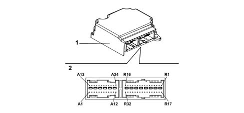
1 - Electronic control unit
2 - Connector pin out
CONTROL UNIT PIN OUT
FRONT CONNECTOR
| PIN | FUNCTION |
|---|---|
| A1 | EARTH |
| A2 | E.C.S. SENSOR EARTH |
| A3 | AVAILABLE FOR 2ND ECS / COMMUNICATION SENSOR SUPPLY |
| A4 | ECS / COMMUNICATION SENSOR SUPPLY |
| A5 | CRASH OUTPUT |
| A6 | SERIAL LINE K FOR TESTER |
| A7 | AIR BAG DEACTIVATED LIGHT |
| A8 | FAILURE LIGHT |
| A9 | DRIVER'S SEAT BELT FASTENED/NOT FASTENED LED |
| A10 | PASSENGER BAG DISABLING KEY (-) |
| A11 | PASSENGER BAG DISABLING KEY (+) |
| A12 | SUPPLY (+15V) |
| A13 | RIGHT REAR PRETENSIONER (+) |
| A14 | RIGHT REAR PRETENSIONER (-) |
| A15 | LEFT REAR PRETENSIONER (+) |
| A16 | LEFT REAR PRETENSIONER (-) |
| A17 | PASSENGER AIR BAG 2ND STAGE (+) |
| A18 | PASSENGER AIR BAG 2ND STAGE (-) |
| A19 | DRIVER'S AIR BAG 2ND STAGE (+) |
| A20 | DRIVER'S AIR BAG 2ND STAGE (-) |
| A21 | PASSENGER AIR BAG 1ST STAGE (+) |
| A22 | PASSENGER AIR BAG 1ST STAGE (-) |
| A23 | DRIVER'S AIR BAG 1ST STAGE (+) |
| A24 | DRIVER'S AIR BAG 1ST STAGE (-) |
REAR CONNECTOR
| PIN | FUNCTION |
|---|---|
| R1 | DRIVER'S SEAT BELT PRETENSIONER (-) |
| R2 | DRIVER'S SEAT BELT PRETENSIONER (+) |
| R3 | PASSENGER SEAT BELT PRETENSIONER (-) |
| R4 | PASSENGER SEAT BELT PRETENSIONER (+) |
| R5 | DRIVER'S SIDE AIR BAG (-) |
| R6 | DRIVER'S SIDE AIR BAG (+) |
| R7 | DRIVER'S SIDE BLIND AIR BAG (-) |
| R8 | DRIVER'S SIDE BLIND AIR BAG (+) |
| R9 | PASSENGER SIDE AIR BAG (-) |
| R10 | PASSENGER SIDE AIR BAG (+) |
| R11 | PASSENGER SIDE BLIND AIR BAG (-) |
| R12 | PASSENGER SIDE BLIND AIR BAG (+) |
| R13 | LEFT REAR SIDE AIR BAG (-) |
| R14 | LEFT REAR SIDE AIR BAG (+) |
| R15 | RIGHT REAR SIDE AIR BAG (-) |
| R16 | RIGHT REAR SIDE AIR BAG (+) |
| R17 | EARTH |
| R18 | AVAILABLE FOR DRIVER CLASSIFICATION INPUT |
| R19 | PASSENGER CLASSIFICATION INPUT |
| R20 | DRIVER'S BUCKLE SWITCH |
| R21 | PASSENGER BUCKLE SWITCH |
| R22 | DRIVER'S AND PASSENGER BUCKLE SWITCH EARTH |
| R23 | REAR BAGS DEACTIVATED LED |
| R24 | DRIVER'S SIDE IMPACT / COMMUNICATION SENSOR SUPPLY |
| R25 | PASSENGER IMPACT / COMMUNICATION SENSOR SUPPLY |
| R26 | DRIVER'S IMPACT SENSOR EARTH |
| R27 | PASSENGER IMPACT SENSOR EARTH |
| R28 | NOT USED |
| R29 | NOT USED |
| R30 | SWITCH FOR DISABLING REAR BAGS (+) |
| R31 | SWITCH FOR DISABLING REAR BAGS (-) |
| R32 | NOT USED |
The Pin Out described refers to the trim level with Air Bags and all optional safety equipment
SYSTEM AUTODIAGNOSIS
The control unit carries out a continuous autodiagnosis of the system operation. In particular:
- it detects and memorizes any faults
- it recognizes the various components and the type of fault;
- it signals the onset of these faults via the special warning light in the instrument panel.
The faults memorised in the control unit may only be deleted after the fault has been repaired using the EXAMINER diagnostic equipment.
If a fault is detected in the passenger Air Bag disabling switch, for safety reasons this is considered by the control unit to be in the OFF position, so the operation of the module is inhibited and the warning light on the instrument panel comes on.
DRIVER'S AIR BAG MODULE
The diagram below shows the driver's Air Bag module
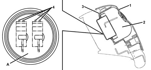
1 - Cover
2 - Bag
3 - Casing
4 - Points of connection to electrical system
A - view of connections
SPECIFCATIONS
The Air Bag is a passive safety device made up of a bag which, in the case of a frontal impact, automatically inflates placing itself between the body of the driver and the structure of the front part of the passenger compartment. The Air Bag module is installed in the centre of the steering wheel, and its cover also acts as the horn control.
COMPOSITION
The module consists of:
- a plastic cover; which in the case of activation tears in predefined points to allow the bag to expand correctly;
- a bag, with a volume of about 55 litres, made of nylon fabric to minimise skin abrasions in the case of contact, and folded in a particular way so that it inflates gradually and not directly facing the driver;
- a hybrid type gas generator (98% Argon, 2% Helium);
- a casing.
On the bottom of the gas generator, there is a warning plate which gives the instructions for handling (See assembly 5580C air bag system).
OPERATION
The Bag is inflated by a gas generator which has two intervention stages which can be activated separately depending on the severity of the impact.
The gas generator is activated by means of two propellant charges which release the compressed gas allowing the bag to expand. The two pyrotechnic charges are activated in sequence: the difference in time between the activation of the first and second charges determines the Bag inflation energy which can be either maximum energy if the difference in time is short or minimum energy where this difference is longer (in any case these periods of time refer to tens of thousandths of a second).
Depending on the extent of the impact, whether or not the seat belts are fastened and (passenger side only) the weight of the passenger, the control unit activates the Air Bag in accordance with the two intervention modes; if the impact is not very serious, the system can opt to inflate the Bag with a minimum energy level to prevent the Bag from harming the driver/passenger when it inflates.
When fully inflated, the cushion is in the optimum position to carry out its function to retain the occupant. The bag deflates immediately thanks to the holes present in the lower part of the bag. These holes also perform the function of 'softening' the contact between the passenger and the bag preventing the risk of abrasions.
PASSENGER AIR BAG MODULE
The following figure shows a view of the assembly
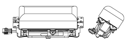
SPECIFCATIONS
The passenger Air Bag flap is in the top part of the dashboard so that ithe bag is forced out towards the windscreen rather than towards the occupant and expands later on in the best position for suitable protection. As for the driver's module, it intervenes to provide front protection for the passenger, in the event of crashes which exceed a particular threshold, and can also be specifically disabled.
COMPOSITION
The module consists of:
- a metal mounting containing the hybrid gas generator and bag;
- a card cover which, in the case of activation, tears to allow correct expansion of the bag;
- a bag, with a volume of about 90 litres, made of nylon fabric (PA 6.6) in order to minimise skin abrasions in the event of contact, and folded in a particular way;
- a gas generator consisting of a pressurised hybrid gas (98% Argon, 2% Helium) container holding a pyrotechnic charge;
- a point for connection to the electrical system;
On the bag cover there is a warning plate which gives the handling instructions (see See assembly 5580C air bag system).
OPERATION
The Bag is inflated by a gas generator which has two intervention stages which can be activated separately depending on the severity of the impact. The passenger Bag activation logic is similar to that of the driver's (see driver's Air Bag) but differs through the presence of the weight sensor which, using a special control unit, analyzes the quantity and the distribution of the occupant's weight and sends this information to the Air Bag system control unit where, on the basis of the signal, it commands the two intervention stages.
The increase in the bag volume tears through the flap in the dashboard at pre-defined points. When fully inflated, the bag is in the optimum position for carrying out its function of protecting the occupant.
The Bag deflates immediately after inflation with the gas thanks to the holes.
SIDE BAG MODULE
The figure below shows a view of assembly.
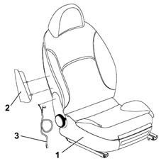
1 - Front seat cover
2 - Side Air Bag module (Side Bag)
3 - Supply cable
SPECIFCATIONS
To provide maximum protection in the event of side impacts, there are optional side Air Bag modules for the front seats and rear seats.
The front modules are fitted on the seat backrests, on the side facing the outside of the vehicle, under the cover, whilst the rear modules on the sides of the backrest always guarantee maximum protection of the chest even on vehicles with sliding rear seats.
This conformation is considered to be the most efficient as it always enables the Air Bag to be in the optimum position in relation to the occupant, irrespective of the seat adjustment or size of the occupant.
The Side Bags are the chest type to mainly protect critical body areas such as the ribs and abdomen.
Do not put covers on the front seat squabs.
Do not wash the seat squab with water or pressurised steam.
COMPOSITION
The side Air Bag module consists of a plastic container holding the gas generator and a permeable nylon bag with a volume of about 12 litres.
The module's container has a cover with predetermined break zones which, with the seat squab cover fitted, line up with easy-open sections of seam on the outside of the seat cover.
On the bottom of the container, there is a warning plate which gives the instructions for handling the module.
The module is connected to the electrical system by means of two cables with a yellow coloured outer casing housed, together with the earth connecting cable for the seat, in a protective duct, secured to the seat structure. The two cables end in a yellow connector. The connectors for the module, the seat belt fastened sensor (driver's side only) and the heater pad (if fitted) are secured to a removable support fitted at the base of the actual seat.
OPERATION
The gas generator for inflating the module is electrically activated by a signal coming from the electronic control module. Following this siganl, a pyrotechnic charge is triggeed which causes the gases contained in the generator to expand. The gases expand, coming out of specific holes, and inflate the bag. The increase in volume of the bag causes the container to break in the predetermined areas and the seams on the seat squab cover to open along the preset sections, thus enabling the bag to come out correctly. After completion, the bag is in the optimum position for carrying out its function of protecting the occupant. After being inflated by the gas, the bag deflates immediately thanks to the permeability of the fabric.
No operations, other than removing and refitting the seat from the vehicle, can be carried out on a seats equipped with a Side Bag. It is absolutely prohibited to disassemble seats fitted with a Side Bag; these operations should be carried out by suitably trained and authorized personnel.
CURTAIN SIDE AIR BAG MODULE (WINDOW BAG)
General view
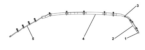
1 - Connector
2 - Gas generator
3 - Bag retaining bands
4 - Bag
5 - Strap
SPECIFCATIONS
On all versions of the car, there is a system for protecting the heads of the front and rear side occupants.
Apart from the vehicle's structural characteristics, the Side Bags are the only passive protection system in the case of a side impact. The head protection Air Bags (Window Bags), in addition to the Side Bags and front Air Bags, offer the rear seat occupants the maximum possible protection in the event of a crash, also eliminating the risk of injuries to the arm and shoulder and protecting the heads of the rear side seat occupants.
Among the different types of Window Bag, the curtain system is the one which offers the best performance thanks to the large area of expansion and its self-supporting capacity, also in the absence of support if the side windows break during the impact.
COMPOSITION
The Window Bag module consists of:
- a gas generator secured by appropriate mounting to the car's rear pillar;
- a permeable fabric flexible tube, secured by a band to the gas generator, which diffuses the gas evenly along the whole length of the bag;
- a bag, with a volume of about 21 litres, secured to the gas generator together with the flexible pipe, is made of a nylon permeable fabric and is folded inside a containing sleeve. The bag is designed so that, when inflated, it correctly absorbs the energy of the impact, holding the heads of the occupants an appropriate distance from the impact zone. After inflation, the gas deflates immediately through the porous fabric.
- plastic easy-open clamps for securing the bag to the ceiling longitudinal member;
- a retaining strap which holds the inflated bag in position;
- a connector for connection to the electrical system;
- a warning plate which gives the instructions.
OPERATION
The gas generator for inflating the module is electrically activated by a signal coming from the electronic control module. Following this siganl, a pyrotechnic charge is triggeed which causes the gases contained in the generator to expand. The gases expand and emerge through specific holes and are distributed evenly along the length of the bag via the flexible pipe, inflating the bag. The increase in volume of the bag causes the retainers to break, the sleeve seams to yield and the finishing trim to open, designed so as to allow the bag to emerge correctly downwards. The correct unfolding of the bag is ensured by a retaining strap, present at the front end of the bag. After completion, the bag is in the optimum position for carrying out its function of protecting the occupant. After inflation, the bag deflates immediately because of the permeability of the fabric.
CLOCK SPRING
The diagram below illustrates the clock spring
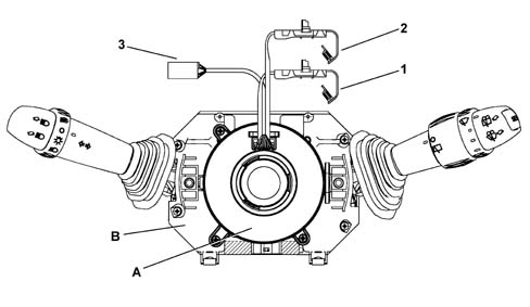
1 - Electrical connection for Air Bag first stage (green)
2 - Electrical connection for Air Bag second stage (yellow)
3 - Steering wheel electrical functions cable
A - Clock spring
B - Steering column switch unit
SPECIFCATIONS
The clock spring makes it possible to transmit the rotation of the steering wheel to the release mechanism inside the casing, transfer the electrical signal for the controls on the steering wheel (horn and other optional control) and connect the Air Bag module with danger of breaking.
The device, consisting of two plates is secured by means of the lower plate to the stalk unit, and is joined to the steering wheel by means of specific recesses on the upper plate. The module connecting cables and the horn buttons are wound around inside the two plates allowing them to follow the movement of the steering wheel.
COMPOSITION
The clock spring on the steering wheel has three cables, two of which is for connecting the Air Bag module (first and second stage) and one of which is for connecting the steering wheel electrical functions (horn, radio controls).
On the upper plate, steering wheel side, there is a ring which automatically blocks the rotation between the two plates when the device is removed from the steering wheel.
The new device is supplied with a safety key for transport. This key should be removed before fitting.
OPERATION
Inside the two plates, the connecting cables for the Air Bag module and the various electrical functions are wound in a spiral, with a sufficient number of coils to follow the steering wheel's rotations. The upper plate rotates by means of the recesses present inside the locking ring which fit in the seating on the steering wheel hub. In the working position, the steering wheel presses on the ring, freeing it from the recesses, thus unlocking the rotation between the two plates. When the steering wheel is removed, pushed by a spring, it blocks the rotation between the two plates. This function prevents the top plate, no longer locked to the steering wheel, from turning freely and causing the sprial inside the device to unwind or wind and then possibly break.
In operations involving the removal of the steering wheel and the device, the following must be observed:
- always operate with the wheels lined up straight;
- lock the two plates with a band, for safety reasons, before removing the device from the steering column switch unit.
If for any reason the upper plate rotates in relation to the lower plate so much that the original position cannot be identified with absolute certainly, the clock spring MUST be replaced (5580C12 clock spring for air bag module on steering wheel r r).
SPECIFCATIONS
The diagram below illustrates the front impact sensor (on the vehicle)
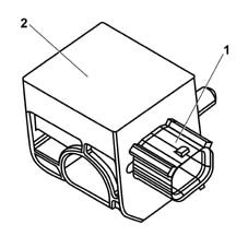
1 - E.C.S. connector
2 - E.C.S.
SPECIFCATIONS
The E.C.S. additional deceleration sensor (Early Crash Sensor) is located at the front of the vehicle, in the area above the radiator, and has the task of assisting the main electronic control unit to anticipate the intervention of the Air Bags, allowing them to be completely unfolded even before the occupant starts moving forwards in relation to the steering wheel or the dashboard.
Take great care not to strike it, damage it or disconnect it during vehicle maintenance operations with the bonnet open.
SIDE IMPACT SATELLITE SENSORS
View of sensor
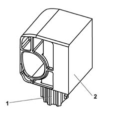
1 - Side impact satellite sensor
2 - Connecting connector
SPECIFCATIONS
Apart from the Air Bags, the side protection system also comprises the electronic control module which ensures correct operation. To measure the acceleration resulting from a side impact, there are two satellite sensors installed in the centre pillars, containing an accelerometer and an electronic control unit.
COMPOSITION
The side impact satellite sensor consists of a casing containing the acceleration sensor. At the rear of the casing, there is a pin for correct positioning in the seating. On the casing, there is also a connection point for connection to the electrical system.
OPERATION
If the acceleration value measured by the sensor in question and processed internally by a specific algorithm causes a particular threshold to be exceeded, the sensor sends the control unit a sinal to active the appropriate side protection system and this information is compared with the measurement obtained from the safing sensor contained in the Air Bag system's electronic control unit. If the values measured are consistent, the control unit causes the activation of the Air Bags on the side affected by the impact.
SPECIFCATIONS
The diagram below illustrates the weight classification sensor
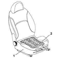
1 - Seat;
2 - Passenger weight sensor with control unit integrated;
SPECIFCATIONS
The O.C. (Occupant Classification) sensor system has been designed to prevent the full power of the Bag from being used, even in the case of extremely serious impacts, when the mass of the occupant, and therefore their kinetic energy, is small. The sensor in questiuon detects and defines the weight classification of the occupant of the seat using a special algorhythm and sends this information to the control unit.
COMPOSITION
The passenger classification sensor is fitted in the right seat between the cushion foam and the outer upholstery.
The system also has a dedicated control unit, installed under the base of the passenger seat.
OPERATION
The greater the distance of the passenger from the dashboard, compared with the driver, suggests that the full power of the Bag should not be used, even for very serious impacts, when the mass of the occupant and therefore their kinetic energy is limited. A special control unit, with 64 detection cells, analyzes the quantity and the distribution of the occupant's weight memorizing the best profile and sends information to the Air Bag system control unit which, on the basis of the signal received, commands the passenger Bag intervention stages. If there is no occupant in the passenger seat or there are inanimate objects, the sensor completely inhibits the activation of the passenger Air Bag and the pretensioner preventing the component from having to be replaced unnecessarily when the vehicle is repaired.
In the control unit logic, the manual disabling always has priority over the seat sensor. In other words, the sensor signals are not taken into consideration by the control unit if the manual disabling key is in the OFF position.
PASSENGER AIR BAG DISABLEMENT KEY SWITCH
View of location on car
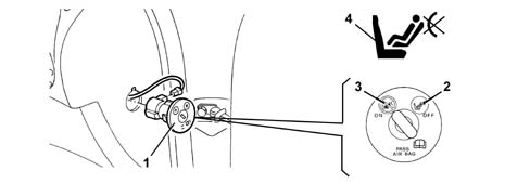
1 - Key switch
2 - OFF position: passenger's Air Bag disabled
3 - ON position: passenger's Air Bag enabled
4 - Passenger's Air Bag disabled warning light
SPECIFCATIONS
A switch operated by the ignition key allows the passenger's Air Bag module to be enabled (ON) or disabled (OFF). This switch is located on the right side panel (left on right hand drive versions) of the dashboard.
In this case, the control unit excludes the activation of the passenger Air Bag, but enables the operation of the pretensioner (only if the seat belt is fastened - because if the occupant is not strapped in the pretensioner is not activated). This is designed to offer minimum protection to a passenger correctly strapped in if the Air Bag is incorrectly deactivated; this deactivation is signalled by a special warning light in the instrument panel coming on.
COMPOSITION
The diagram shows a view of the assembly.
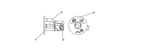
1 - Casing
2 - Switch
3 - Key barrel
4 - Plate
COMPOSITION
The unit consists of a casing containing the switch, a key barrel inserted in the casing and held by a clip and a plate which indicates the position assumed by the switch (ON or OFF). On the casing, there is also the seating for the connector to the electrical system.
Any faults in the switch are indicated by the Air Bag system fault warning light coming on.
OPERATION
The switch can be operated by the car's ignition switch whenever the activation of the passenger's front module is to be enabled or disabled.
The electronic control unit checks the status of the switch during the normal diagnostic procedure at Key On (four seconds). If the recognised state is OFF, it excludes the module from possible activation, memorises the corresponding signal and causes the passenger Air Bag disabled warning light on the instrument panel to come on. If the recognised state is ON, after the four seconds of the diagnostic procedure the warning light flashes for a further four seconds and then goes out.
The remaining side Air Bags are not affected by deactivation commands.
In the case of faults in the switch, the system ensures the following:
- it does not activate the passenger module
- it causes the Air Bag fault warning light to come on
- it causes the passenger Air Bag disabled warning light to come on
- it memorises the state of deactivation.
Do not operate the switch with the ignition key in the ON position (e.g. by using the second key). In this case the electronic control unit would memorise a fault, indicating it by switching on the Air Bag fault warning light and deactivating the module.
SPECIFCATIONS
A switch operated by the ignition key makes it possible to enable (ON) or disable (OFF) the rear seat Side Bag modules. This switch is located in the luggage compartment on the right hand side near the current socket.
COMPOSITION
The diagram shows a view of the assembly.
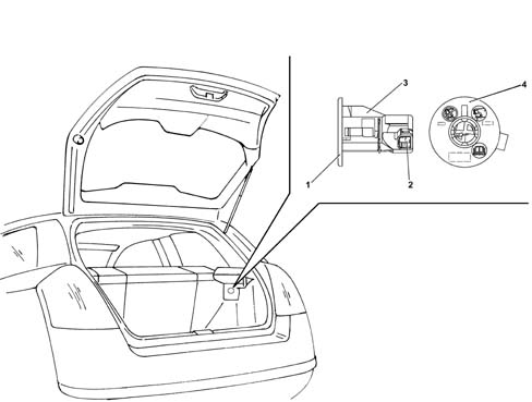
1 - Casing
2 - Switch
3 - Key barrel
4 - Plate
COMPOSITION
The unit consists of a casing containing the switch, a key barrel inserted in the casing and held by a clip and a plate which indicates the position assumed by the switch (ON or OFF). On the casing, there is also the seating for the connector to the electrical system.
Any faults in the switch are indicated by the Air Bag system fault warning light coming on.
OPERATION
The switch can be operated by the car's ignition switch whenever the activation of the rear seat Side Bag modules is to be enabled or disabled.
The electronic control unit checks the status of the switch during the normal diagnostic procedure at Key On (four seconds) in exactly the same way as for disabling the front Side Bags.
Do not operate the switch with the ignition key in the ON position (e.g. by using the second key). In this case the electronic control unit would memorise a fault, indicating it by switching on the Air Bag fault warning light and deactivating the module.
SPECIFCATIONS
The pretensioners are pyrotechnic devices, electrically activated by a signal coming from the electronic control unit, integrated in the front and rear side seat belt reels.
The intervention of the pretensioners in the case of a frontal impact which exceeds a particular threshold, causes any slack in the seat belt to be taken up, thus holding the occupant as closely as possible to the seat squab.
OPERATION
The diagram below shows the pretensioner mechanism
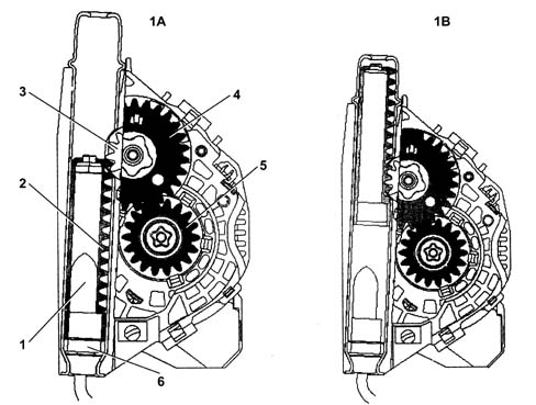
1A - Before activation
1B - After activation
1 - Gas generator
2 - Rack piston
3 - Toothed wheel 3
4 - Toothed wheel 4
5 - Toothed bush
6 - Pyrotechnic charge
OPERATION
The moment the vehicle deceleration is sufficiently high, the electronic sensor located in the control unit sends a signal which primes the pyrotechnic charges for the gas generators (6). The burning of the propellant (1) produces a chemical reaction creating (inert) gas whose pressure creates a force which thrusts the rack pinion (2) upwards. The latter causes the toothed wheel (3), connected to the toothed wheel (4) to rotate; The ring gear meshes with the toothed bush (5) changing the rotary movement of the spindle to the opposite direction to the unwinding of the seat belt, rewinding it by several centimetres.
The special seat belt fastened sensors (O.L. sensors) located in the front seat belt buckles, allow the control unit to detect whether or not the seat belt is fastened and to suitably adapt the activation of the Bags and prevent the activation of the pretensioners (which, if the seat belts were not fastened, would constitute an additional cost when the vehicle is repaired).
Once the pretensioners have intervened, the seat belts remain locked and must be replaced.
AIR BAG SIGNALLING WARNING LIGHTS
View of position of warning lights in instrument panel
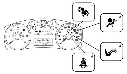
1 - Rear Air Bag disablement
2 - Air Bag system failure signal
3 - Passenger Air Bag disablement
4 - driver's seat belt fastened signal
AIR BAG SIGNALLING WARNING LIGHTS
During starting, key in key-on position, the fault warning light (2) (red) comes on for about four seconds (initial self-test stage) and then goes out. If the control unit detects a fault in the warning light, it memorises the corresponding fault code. If no faults are detected in the system at key-on, and there are no fault conditions in the fault memory, the warning light goes out after four seconds of self-test, otherwise it stays on until key off.
The warning light remains on or comes on, during the normal operation of the vehicle, in the following cases:
- the control unit detects a fault in the Air Bag system;
- the control unit detects an impact with activation of the system;
- the control unit detects a fault in the actual warning light connection circuit.
As a result of an impact with the intervention of only the pretensioners or side Air Bags, the warning light stays on until the system's operating conditions are restored (replacement of the component concerned and rest of the control unit using the EXAMINER).
if the impact causes the intervention of the front Air Bag modules, the warning light stays on permanently, and the control unit cannot be reset (in this case the control unit must be replaced).
If internal operating faults arise during the control unit's operating life, and these faults cannot be reset by the EXAMINER, they are indicated by the warning light staying on permanently.
With the key at the key-on position, the passenger Air Bag disabled warning light (3) (yellow) comes on for about four seconds (initial self-test stage). If the control unit detects a fault in the warning light, it memorises the relevant fault code, switches on the fault warning light and keeps the passenger's Air Bag module disabled. Restore the system's operation using the EXAMINER, in the same way as for the fault warning light.
After the initial four-second self-test stage, if the disabling key switch is turned to the OFF position, the warning light stays on indicating that the passenger's module is disabled. If there are no faults, the light flashes for a further four seconds and then goes out, indicating that the passenger's module is enabled.
The passenger's module MUST be disabled only using the ignition key (ignition switch at STOP position) - (DO NOT USE a second ignition key for disablement).
With the ignition key in the Key On position, the rear Side Bag disabled warning light (1) is yellow and the activation logic faithfully mirrors that of the passenger disabling warning light coming on for four seconds.
AIR BAG SIGNALLING WARNING LIGHTS
The driver's seat belt fastened warning light (4) comes on permanently when the driver's seat belt is not correctly fastened and the ignition is switched ON.
AIR BAG SIGNALLING WARNING LIGHTS
The SBR function (Seat Belt Reminder) comprises a horn which, together with the 'seat belt' warning light in the instrument panel flashing, warns the driver that their seat belt is not fastened.
The acoustic signal lasts a maximum of 90 seconds. After this length of time, the acoustic signal is interrupted and the 'seat belts' warning light remains on constantly.
The acoustic and visual signals are activated in the presence of at least one of the following conditions:
- time of 60 seconds elapsed and vehicle speed detected of more than 10 Km/h;
- vehicle speed more than 25 km/h;
- distance travelled more than 500 m.
If the seat belt is fastened, the function is interrupted and prepares for a new signalling later on.
The horn can be temporarily deactivated (until the engine is switched off the next time) by means of the following procedure, which should be carried out within a minute of turning the ignition ON:
- fasten the driver's seat belt;
- wait at least 20 seconds, then unfasten the driver's seat belt.
Seek assistance from the Fiat Service Network to deactivate it permanently. The SBR system is reactivated using the setup menu in the instrument panel.
SPECIFICATIONS:
The vehicle is equipped with an optional alarm system consisting of:
- Alarm siren (in the engine compartment) connected to the NBC bia the A - BUS serial line
- Trim fitted on the courtesy light with volumetric sensors, anti-tilt sensors and exclusion buttons
- Perimeter sensors (door open switches)
- Transmitter in remote control key
- Receiver in NBC
The following are also designed to alert the user:
- anti-theft on and malfunction signal LED, located in the driver's door panel trim
- Signals giving the causes of the alarm or malfunction via the instrument panel
The NBC, completing the alarm function(the same for all countries) can be programmed, individually, to meet local activation/deactivation blink code and alarm (siren) regulations.
The programming can be altered by the service network to adapt it for a temporary stay in another country.
It is possible, using the exclusion buttons, to separately switch off the volumetric surveillance and/or the anti-lifting surveillance before switching on the alarm.
The partial switching off persists until the next command to unlock the doors / switch off the alarm.
The alarm system carries out perimeter surveillance, volumetric surveillance, surveillance to detect if the vehicle is being tilted (if the sensor is fitted), surveillance to detect if the supply cables are cut and surveillance of the ignition lock barrel.
The engagement of the alarm system is indicated by the direction indicators coming on constantly and a beep from the siren.
When the alarm is switched on, the deterrent LED at the side of the safety knob in the door panel will flash to indicate the surveillance state.
When the system is switched the volumetric protection and/or the anti-tilt protection can be excluded.
When the system is switched off this is signalled by the direction indicators flashing twice and the siren beeping twice. The alarm system is also switched off using an enabled key recognized by the immobilizer and/or the Passive Entry system.
SYSTEM STATES
The operation of the alarm system is managed by the NBC which sends and receives commands from the outside modules via the A - BUS serial line.
Below is a list of the eight possible states for the alarm system:
- DEACTIVATED
- REST
- ON
- SURVEILLANCE
- ALARM
- OFF
- PROGRAMMING
- DIAGNOSIS
Deactivation
This is the state the alarm system is in each time an enabled key or CID is recognized by the immobilizer or the Passive Entry system.
This is the only way to deactivate the alarm if it is impossible to deactivate it using the remote control or CID (the remote key on the siren is no longer fitted); this operation switches the alarm off but not the signals (blinker and LED).
Rest
This is the 'basic' state the alarm system is in and from which it is possible to move to the following states:
- Diagnosis: activated by connection to the NBC using the Examiner.
- Surveillance: through an insertion command when the vehicle needs protecting.
- Deactivation: when an enabled key or CID is recognized by the immobilizer / Passive Entry.
In the 'rest' condition the NBC always controls the + 15 which, if fitted, prevents the move to 'Surveillance' and, especially to 'Alarm', if not fitted, the 'Surveillance' condition is introduced.
The volumetric and anti-tilt sensors can be excluded, in the rest condition, within 1 minute of the key off by pressing the buttons on the courtesy light trim.
Switching on
The switching on operation allows the alarm to move on from the 'Rest' condition to 'Surveillance'.
This operation takes place the moment the doors are locked (using the remote control or Passive Entry) and is signalled, as stated earlier, by the direction indicators coming on at the same times as the siren beeps.
When the NBC receives the command (remote control, Passive Entry) it activates the alarm switching on procedure as follows:
- INDICATION OF SWITCHING ON IN PROGRESS It identifies the operating mode. It activates the diagnosis of the alarm system modules. It gives the go ahead for the visual and acoustic signals when it is switched on.
- SYSTEM DIAGNOSIS The plausibility of the door switches (2 or 4) and the boot and bonnet switches is checked and, if one of these entry points is found NOT to be closed, then it is excluded from the surveillance.
- SENSOR STATE CHECK If the siren is NOT OK after a maximum of 3 seconds the system causes the direction indicators to flash twice. A maximum of 4 seconds after the sysetm has been switched on, the NBC receives OK /NOT OK information from the volumetric sensors module and the anti-tilt sensor. (see signalling modes in next point). If the results for these modules do not arrive within 4 seconds, then the respective module is decreed to be not working signalling an alarm system failure.
- DISPLAY OF DIAGNOSTIC INFORMATION The signalling of faults when the system is switched on takes place through: 1 warning beep 4 seconds after the locking / alarm engagement command. Signalling the type of problem through the deterrent LED as follows: A) flashing at 8 Hz for 2.5 seconds for volumetric faults. B) LED on constantly for 10 seconds for a siren fault or anti-tilt sensor fault. Obviously the system components which are faulty will not be switched on.
- SWITCHING ON SIREN If the siren is working properly the management of the HEART BEAT at the A - BUS serial line will be activated, i.e. a signal which is exchanged every 500 msecs. between the NBC and the siren to constantly check the latter.
Surveillance
During the surveillance state the NBC reads all the signals / commands passing through the CAV (volumetric alarm control unit) and the CSA (anti-theft alarm control unit) A - BUS commanding the siren, via the A - BUS, if these signals / commands require its activation.
The move to the alarm state is activated if the NBC verifies one or more of the following conditions:
- the presence of the + 15 without a prior deactivation command.
- Change in state of the inputs coming from the doors, boot or bonnet (instrusion attempt)
- Command at the A - BUS from outside modules such as the ultrasound sensors, ant-tilt sensor or from the siren (cables cut).
Switching on again
Re-switching on allows the alarm system to change from rest to surveillance automatically when, after switching off by the user, the doors / bonnet / boot are not opened.
The alarm is switched back on taking account of any exclusions of parts of the system carried out at the last switch-on. (volumetric protection, siren, etc.)
If the NBC measures a battery voltage of below 8.5 V for more than 30 minutes, it switches off the external modules in order to safeguard the life of the battery and the possibility of subsequent engine starting.
If the user shows the intention of opening the boot / rearscreen (using the remote control button) and the system is in the surveillance or alarm state, then the NBC disables the volumetric / anti-tilt external modules, disables the boot / rearscreen entry from the perimeter protection (with the door and bonnet lid protection remaining activated) and activates the blinker signals (see: Central Locking System).
If, however, within 1 second of the command (from the remote control) the state of the boot switch does not change, the system switches the protection systems back on again. This timing makes it possible to ensure that the vehicle is protected even if the boot / rearscreen entry system is faulty. If, on the other hand, the boot / rearscreen is left open and the alarm is then switched on, the volumetric / anti-tilt protection system will be switched on.
Alarm
If one of the surveillance sensors identifies a faulty situation (attempted or successful intrusion or theft of the vehicle), the alarm system changes to the alarm state switching on the siren and blinker.
The NBC memorizes the last 10 causes of an alarm.
The following causes of alarm can be memorized:
- alarm from driver's door
- alarm from passenger door
- alarm from left rear door
- alarm from right rear door
- alarm from ultrasound sensor
- alarm from anti-tilt sensor (if fitted)
- alarm from siren cable cutting
- alarm from boot
- alarm from bonnet
- alarm from + 15
- alarm from + 30 cable cutting
- alarm from incorrect communication between NBC and siren control unit (Heart Beat)
- alarm from intrusion at siren with incorrect DSIR command
- alarm from intrustion at external modules with DUS and DAINC command
Switching off
Switching off can take place during either surveillance or an alarm state and is carried out using the remote control or Passive Entry; the NBC commands the alarm system to be switched off the moment the doors are unlocked.
The alarm system can also be switched off in the following ways:
- by turning an enabled key to the ON position
- by detecting the presence of a valid CID in the passenger compartment in the GARAGE position (The latter operation is, for example, necessary when with the CID discharged, the customer oepns the driver's door using the catch and thereby activates the alarm: by placing the CID in the GARAGE position the alarm can be deactivated).
At the first key on the NBC commands the display of any alarms which have taken place via the LED
End of line programming (Proxi)
This programming is carried out in the factory at the end of the line (proxi procedure) and consists of memorizing the configuration of the system fitted on the vehicle in the NBC; in other words the NBC is told whether or not the siren, ultrasound modules and anti-tilt sensor are fitted.
This information can then be read but NOT altered by the Examiner which will adapt its diagnostic procedures depending on the configuration of the vehicle.
On a service level, when the NBC, the siren or the CAV is replaced, the PROXI procedure is not carried out using the Examiner because the NBC arrives already programmed whilst the siren and the CAV do not require the procedure.
During the end of line PROXI the COUNTRY MODE is also memorized (default: EEC) and can be altered by the service network using the Examiner or through the following procedure:
- 1 place the ignition key in the key on position
- 2 activate the hazard warning light flasher
- 3 press the rear fog lamp button and keep it pressed
- 4 using the ignition key carry out the following sequence in strict order: key off (< 2 s), key on (< 1s), key off, starting from the key on state keeping the rear fog lamp button pressed
- 4 at the end of the manoeuvre the siren will beep 5 times to confirm that the programming has been activated
- 5 release the rear fog lamp switch and press it again the same number of times as the desired mode (if the button is pressed for an invalid number of times, the siren will beep 5 times and the procedure will be cancelled)
- 6 turn the ignition key to the key on position within 10 seconds of pressing the rear fog lamp switch for the last time
- 7 the siren will beep the same number of times as the operating mode selected
- 8 at the end of the beeps, turn the ignition key to the key off position: the NBC is programmed for the new operating mode
Below is a list of the different operating modes:
- MODE 1 DEFAULT MODE (EEC)
- MODE 2 (Great Britain)
- MODE 3 (Belgium)
- MODE 4 (Holland)
- MODE 5 (World)
- MODE 6 (Temporary market)
Operating modes table:
| Country | EEC | G.B. | BELGIUM | HOLLAND | WORLD | TEMP | RANGE |
|---|---|---|---|---|---|---|---|
| MODE | 1 | 23 | 3 | 4 | 5 | 6 | 7 |
| NUMBER OF DOOR / BONNET / BOOT / KEY ON ALARM CYCLES | 3 | 8 | 3 | 3 | 3 | X | 31 |
| NUMBER OF VOLUMETRIC AND ANTI-TILT ALARM CYCLES | 3 | 8 | 3 | 3 | 3 | X | 31 |
| NUMBER OF CABLE CUT ALARM CYCLES | 3 | 12. | 3 | 3 | 3 | X | 31 |
| NUMBER OF TOTAL ALARM CYCLES | 10 | 24 | 12 | 12 | 10 | X | 255 |
| PAUSE BETWEEN ALARM CYCLES (S) | 6 | 6 | 4 | 6 | 6 | X | 31s |
| SIREN ALARM TIME (S) | 26 | 26 | 26 | 26 | 26 | X | 255s |
| SIREN POWER (DBA) | 110 | 110 | 110 | 114 | 110 | X | 255DBA |
| TYPE OF ACOUSTIC SIGNAL | CONTINUOUS | CONTINUOUS | CONTINUOUS | CONTINUOUS | CONTINUOUS | X | N/A |
| TYPE OF SIREN SOUND | MODULATED | MODULATED | MODULATED | MODULATED | MODULATED | X | N/A |
| SIREN FREQUENCY MODULATION (HZ) | 2±1 | 2±1 | 2±1 | 2±1 | 2±1 | X | 20Hz |
| SIREN SOUND FREQUENCY (HZ) | 1800-3500 | 1800-3500 | 1800-3500 | 1800-3500 | 1800-3500 | X | 5000Hz |
Cancelling the procedure
The rear fog lamp button is not pressed for 10 seconds whilst entering the operating mode, the procedure is aborted; in this case the siren will beep 5 times to warn the operator and the NBC will maintain the previous operating mode.
Parts & tools for this job For 2001 Fiat Stilo
- TOOLDigital multimeterSearch: automotive digital multimeter
- PARTAssorted fuse kitSearch: car fuse assortment kit
- TOOLWire crimper and connector kitSearch: wire crimper connector kit
Links open Amazon search results in a new tab. As an Amazon Associate I earn from qualifying purchases.