
Piston connecting rod set - r r
- Make
- Fiat
- Model
- Stilo Factory Service Manual
- Year
- 2001–2007
- Section
- Pistons and connecting rods › Piston connecting rod set - r r
Piston connecting rod set - r r
Removing
- 1020A24 crank case oil sump - r + r clean seals for sealant application with engine removed
1. Position the flywheel retainer.
| Name | Country | |
|---|---|---|
| 1 | Counter-torque | 1.860.846.000 |
2. Undo the fixing bolts (2a) and remove the clutch plate (2b).
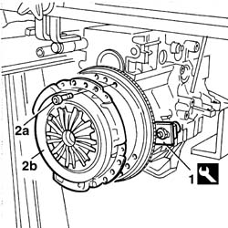
Removing
- 1020A24 crank case oil sump - r + r clean seals for sealant application with engine removed
1. Position the flywheel retainer.
| Name | Country | |
|---|---|---|
| 1 | Counter-torque | 1.860.846.000 |
2. Undo the fixing bolts (2a) and remove the clutch plate (2b).
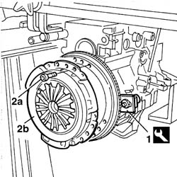
Removing
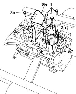
- 1020A24 crank case oil sump - r + r clean seals for sealant application with engine removed.
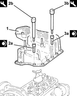
1. Undo the retaining bolts.
2. Remove the engine oil pump (2a) complete with draught element (2b).
Recover the oil pump gasket.
3. Undo the fixing bolt (3a) and remove the section of the engine oil dipstick inside the cylinder block/crankcase (3b).
Removing
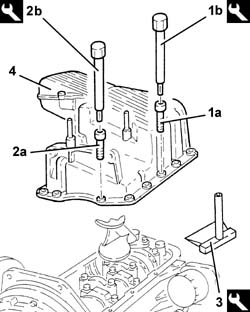
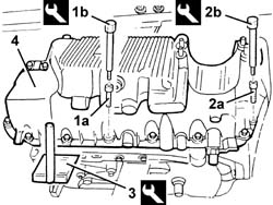
1. Undo the front and rear bolts (1a) for the crankcase sump using the spanner (1b).
| Name | Country | |
|---|---|---|
| 1b | Key | 1.860.834.000 |
2. Undo the side bolts (2a) for the crankcase sump using the spanner (2b).
| Name | Country | |
|---|---|---|
| 2b | Key | 1.860.833.000 |
3. Cut the oil sump sealant using the tool.
| Name | Country | |
|---|---|---|
| 3 | Blade | 1.870.718.000 |
4. Remove the crankcase sump.
Removing
1. Undo the front and rear bolts (1a) for the crankcase sump using the spanner (1b).
| Name | Country | |
|---|---|---|
| 1b | Key | 1.860.834.000 |
2. Undo the side bolts (2a) for the crankcase sump using the spanner (2b).
| Name | Country | |
|---|---|---|
| 2b | Key | 1.860.833.000 |
3. Cut the oil sump sealant using the tool.
| Name | Country | |
|---|---|---|
| 3 | Blade | 1.870.718.000 |
4. Remove the crankcase sump.
Removing
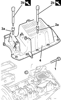
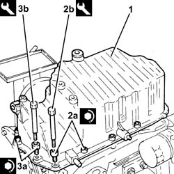
1. Undo the bolt connecting the oil sump to the intermediate shaft support.
2. Undo the front and rear bolts (2a) for the crankcase sump using the tool (2b).
| Name | Country | |
|---|---|---|
| 2b | Key | 1.860.834.000 |
3. Undo the side bolts (3a) for the crankcase sump using the tool (3b).
| Name | Country | |
|---|---|---|
| 3b | Key | 1.860.833.000 |
4. Remove the crankcase sump.
To release the crankcase sump, tap it gently with a a resin hammer, then use a screwdriver to lever on the special projections at the side of the crankcase sump.
Removing
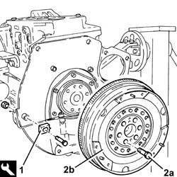
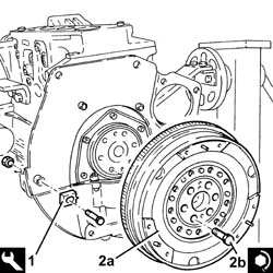
1. Fit the flywheel lock.
| Name | Country | |
|---|---|---|
| 1 | Counter-torque | 1.860.846.001 |
2. Undo the bolts (2a) and remove the engine flywheel (2b).
The engine flywheel retaining bolts are treated with a compound to prevent them coming undone they should therefore be replaced whenever they are removed.
Remove the flywheel lock.
| Name | Country | |
|---|---|---|
| Counter-torque | 1.860.846.001 |
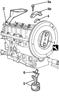
1. Remove the two bolts fixing the engine flywheel and position the tool (1a) for rotating the crankshaft.
| Name | Country | |
|---|---|---|
| 1 | Flange | 1.860.815.000 |
Remove the flywheel lock fitted previously.
2. Undo the bolts and remove the oil inlet from the oil pump.
Rotate the crankshaft using the tool fitted previously until cylinders no. 1 and no. 4 are at T.D.C
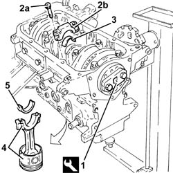
3. Undo the bolts (3a) and remove the big end bearing caps (3b) for cylinders no. 1 and no. 4.
4. Remove the lower connecting rod half bearings for cylinders no. 1 and no. 4.
5. Remove the connecting rod-piston assemblies for cylinders 1 and 4.
6. Remove the upper connecting rod half bearings for cylinders 1 and 4.
Proceed in the same way to remove the pistons and connecting rods for cylinders 2 and 3.
1. Remove the two bolts fixing the engine flywheel and position the tool (1a) for rotating the crankshaft.
| Name | Country | |
|---|---|---|
| 1 | Flange | 1.860.815.000 |
Remove the flywheel lock fitted previously.
2. Undo the bolts and remove the oil inlet from the oil pump.
Rotate the crankshaft using the tool fitted previously until cylinders no. 1 and no. 4 are at T.D.C
3. Undo the bolts (3a) and remove the big end bearing caps (3b) for cylinders no. 1 and no. 4.
4. Remove the lower connecting rod half bearings for cylinders no. 1 and no. 4.
5. Remove the connecting rod-piston assemblies for cylinders 1 and 4.
6. Remove the upper connecting rod half bearings for cylinders 1 and 4.
Proceed in the same way to remove the pistons and connecting rods for cylinders 2 and 3.
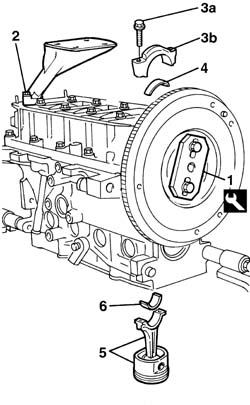
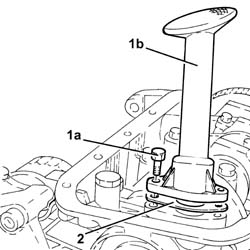
1. Using the service bolts (1a), fit the tool (1b) for rotating the crankshaft.
| Name | Country | |
|---|---|---|
| 1b | Flange | 1.860.815.000 |
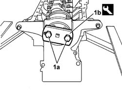
1. Undo the bolts (1a) and remove the oil intake duct (1b) with its gasket (1c).
2. Fit the tool for rotating the crankshaft.
| Name | Country | |
|---|---|---|
| 2 | Flange | 1.860.815.000 |
Rotate the crankshaft using the tool fitted previously until the pistons for cylinders no. 1 and no. 4 are at B.D.C.
3. Undo the bolts (3a) and remove the big end bearing caps (3b) with their bearing shells (3c) of cylinders no. 1 and no. 4.
4. Remove the connecting rod-piston assemblies (4a) complete with bearing shells (4b) for cylinders no. 1 and 4.
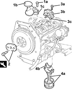
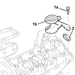
1. Undo the bolts (1a) and remove the engine oil inlet (1b) complete with gasket.
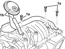
1. Undo the bolts (1a) and remove the engine oil inlet (1b).
2. Remove the gasket.
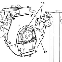
1. Undo the bolts (1a) and remove the engine flywheel protection (1b).
Refitting
Rotate the crankshaft using the tool fitted previously.
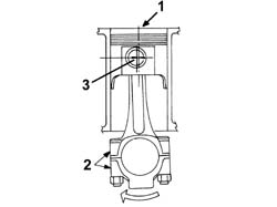
The connecting rod-piston assemblies are fitted with the references in the following positions.
1. Piston grade and arrow indicating the timing side.
2. Area where number of cylinder bore/liner to which the connecting rod belongs is stamped.
3. Connecting rod pin offset.
The letters for the cylinder bore/liner class are located on the cylinder block/crankcase.
Refitting
Rotate the crankshaft using the tool fitted previously.
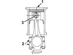
The connecting rod-piston assemblies are fitted with the references in the following positions.
1. Piston grade and arrow indicating the timing side.
2. Area where number of cylinder bore/liner to which the connecting rod belongs is stamped.
3. Connecting rod pin offset.
The letters for the cylinder bore/liner class are located on the cylinder block/crankcase.
1. Undo the fixing bolts (1a) and remove the connecting rod cap (1b).
2. Remove the lower big end bearing shell.
3. Remove the connecting rod - piston assembly.
4. Remove the upper big end bearing shell.
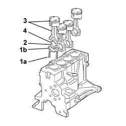
Do the same to remove the connecting rod-piston assemblies of cylinders no. 2 and no. 3.
Fit the tool for rotating the crankshaft and rotate the crankshaft so that the connecting rod caps are accessible.
| Name | Country | |
|---|---|---|
| Flange | 1.860.815.000 |
1. Undo the bolts (1a) and remove the connecting rod caps (1b) and half-bearings (1c).
2. Remove the piston-connecting rod assemblies (2a) complete with half-bearings (2b).
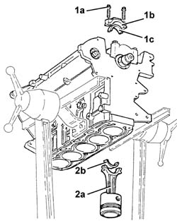
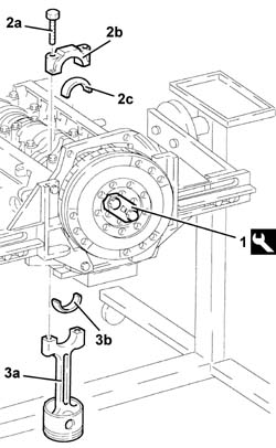
1. Fit the tool and rotate the crankshaft until the cylinder concerned is at B.D.C.
| Name | Country | |
|---|---|---|
| 1 | Flange | 1.860.815.000 |
2. Undo bolts (2a) and remove big end bearing caps (2b) complete with bearing shells (2c).
3. Remove the connecting rod-piston assembly (3a), complete with half-bearing (3b).
Proceed in the same way with the removal of the pistons and connecting rods for the remaining cylinders.
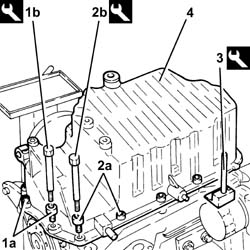
1. Undo the front and rear bolts (1a) securing the crankcase sump using tool (1b).
| Name | Country | |
|---|---|---|
| 1b | Spanner | 1.860.833.001 |
2. Undo the side bolts (2a) securing the crankcase sump using tool (2b).
| Name | Country | |
|---|---|---|
| 2b | Spanner | 1.860.834.001 |
3. Use the tool to cut the crankcase sump sealant.
| Name | Country | |
|---|---|---|
| 3 | Blade | 1.870.718.000 |
4. Remove the crankcase sump.
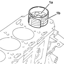
1. Fit the connecting rod-piston assemblies (1a), complete with half-bearings, using the tool (1b) for compressing the piston rings and later introducing the piston in the liner/bore.
| Name | Country | |
|---|---|---|
| 1b | Fitting tool | 1.860.700.000 |
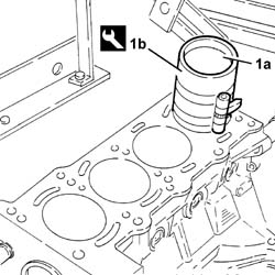
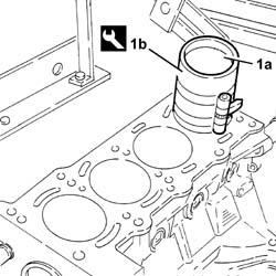
1. Fit the connecting rod-piston assemblies (1a), complete with half-bearings, using the tool (1b) for compressing the piston rings and later introducing the piston in the liner/bore.
| Name | Country | |
|---|---|---|
| 1b | Fitting tool | 1.860.700.000 |
Refitting
Rotate the crankshaft using the tool fitted previously.
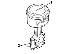
1. The connecting rod-piston assemblies are fitted with the engine rotation arrow stamped on the piston crown facing the inlet side.
2. Check that the stamps for the cylinder bore/liner to which the connecting rod belongs are on the exhaust side.
Refitting
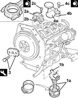
1. Replace the connecting rod-piston assemblies (1a) complete with bearing shells (1b) of cylinders no. 2 and 3
Fit the connecting rod - piston assembly in the crankcase with the large grooves (for the inlet valves) on the piston crowns facing towards the inlet side.
2. Fit the big end bearing caps (2a) complete with bearing shells (2b) and tighten the bolts (2c) to torque.
The connecting rod caps are fitted so that the number stamped on them is facing the same side as the one stamped on the big end (inlet side).
| Fastening | Component | Ø | Value (daNm) | |
|---|---|---|---|---|
| 2c | Bolt | BIG END BEARING CAPS | M9 | 2.5 + 60° |
Do the same to fit the connecting rod-piston assemblies of cylinders no. 1 and no. 4.
3. Remove the tool for rotating the crankshaft.
| Name | Country | |
|---|---|---|
| 3 | Flange | 1.860.815.000 |
4. Fit the intake duct (4a) complete with gasket (4b) and fix it using the bolts (4c) to the specified torque
| Fastening | Component | Ø | Value (daNm) | |
|---|---|---|---|---|
| 4c | Bolt | OIL SECTION PUMP | M7 | 1.3 - 1.6 |
Refitting
Place the piston-connecting rod assemblies, complete with half-bearings, back in their housings.
Use a suitable tool for compressing the seals and then introducing them in the cylinder liner/bore.
Fit the connecting rod - piston assembly in the crankcase with the large grooves (for the inlet valves) on the piston crowns facing towards the inlet side.
Place the connecting rod bearing caps, complete with half-bearings, back in their housings and fix them tightening the bolts to the recommended torque.
The connecting rod caps are fitted so that the number stamped on them is facing the same side as the one stamped on the big end (inlet side).
| Fastening | Component | Ø | Value (daNm) | |
|---|---|---|---|---|
| Bolt | BIG END BEARING CAPS | M9 | 2.0 + 60° |
Use the tool for angular tightening of the connecting rod cap bolts.
| Name | Country | |
|---|---|---|
| Protractor | 1.860.942.000 |
Remove the tool for rotating the crankshaft.
| Name | Country | |
|---|---|---|
| Flange | 1.860.815.000 |
Place the engine oil inlet, complete with gasket, back in its housing and secure it using the bolts.
Clean the matching surfaces of crankcase sump and cylinder block.
Apply silicon sealant around the edge of the crankcase sump.
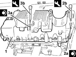
1. Refit the crankcase sump
2. Tighten the side bolts (2a) for the crankcase sump to the recommended torque using the spanner (2b).
| Fastening | Component | Ø | Value (daNm) | |
|---|---|---|---|---|
| 2a | Side bolt | OIL SUMP | M6 | (Engine block side) 0.9 - 1.2 |
| Name | Country | |
|---|---|---|
| 2b | Key | 1.860.833.000 |
3. Tighten the front and rear bolts (3a) for the crankcase sump to the recommended torque using the spanner (3b).
| Fastening | Component | Ø | Value (daNm) | |
|---|---|---|---|---|
| 3a | Front and rear bolt | OIL SUMP | M8 | (Engine crankcase side) 2.3 ÷ 3.3 |
| Name | Country | |
|---|---|---|
| 3b | Key | 1.860.834.000 |
Refitting
Rotate the cylinder block through 90° on the overhauling stand.
Rotate the crankshaft using the tool fitted previously until the cylinder concerned is at B.D.C.
Select the connecting rod bearing halves as described under - 1024A10 crank shaft - r + r with engine removed - check main and connecting rod bearingand replace if necessary.
1. Fit the piston - connecting rod assembly (1a), complete with half-bearing, using the tool (1b).
The connecting rod - piston assemblies are fitted in the cylinder block/crankcase with the combustion chamber in the piston facing the inlet side.
2. Fit the big end bearing cap (2a) complete with half-bearing and fix it using the bolts (2b) without tightening them.
The connecting rod caps are fitted so that the number stamped on them is facing the same side as the one stamped on the big end (inlet side).
Work in the same way when refitting the pistons and connecting rods for the remaining cylinders.
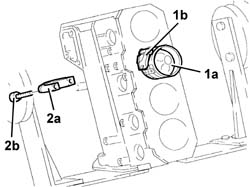
1. Undo the bolts (1a) and remove the engine oil inlet (1b).
2. Remove the gasket.
Rotate the engine on the overhauling stand.
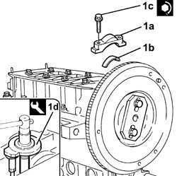
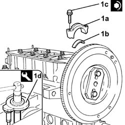
1. Fit the connecting rod caps (1a), complete with half-bearings (1b), and fix them tightening the bolts (1c) to the recommended torque using tool (1d) for the angular tightening.
The connecting rod caps are fitted so that the number stamped on them is facing the same side as the one stamped on the big end (inlet side).
| Fastening | Component | Ø | Value (daNm) | |
|---|---|---|---|---|
| 1c | Bolt | CONNECTING ROD CAP FASTENERS | M8 | 2 + 40° |
| Name | Country | |
|---|---|---|
| 1d | Protractor | 1.860.942.000 |
Rotate the engine on the overhauling stand.
1. Fit the connecting rod caps (1a), complete with half-bearings (1b), and fix them tightening the bolts (1c) to the recommended torque using tool (1d) for angle tightening.
The connecting rods come with split caps. if replaced, they are supplied pre-split by the manufacturer. Check that the components are free of burrs, blisters, scratches or any type of surface defect. Before installation, the parts must be thoroughly washed, cleaned and dried. The connecting rod caps are fitted so that the number stamped on them is facing the same side as the one stamped on the big end (inlet side).
Each connecting rod must be matched with its own cap, respecting the printed reference numbers. connecting rods and connecting rod caps are not interchangeable.
| Fastening | Component | Ø | Value (daNm) | |
|---|---|---|---|---|
| 1c | Bolt | CONNECTING ROD CAP FASTENERS | M8 | 2 + 40° |
| Name | Country | |
|---|---|---|
| 1d | Protractor | 1.860.942.000 |
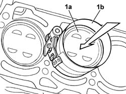
1. Fit the connecting rod-piston assembly (1a), complete with half-bearing, using the tool (1b) for compressing the piston rings and the subsequent introduction of the piston in the liner/bore.
Clean the matching surfaces of crankcase sump and cylinder block.
Apply silicon sealant around the edge of the crankcase sump.
1. Refit the crankcase sump
2. Tighten the side bolts (2a) for the crankcase sump to the recommended torque using the spanner (2b).
| Fastening | Component | Ø | Value (daNm) | |
|---|---|---|---|---|
| 2a | Side bolt | OIL SUMP | M6 | (Engine crankcase side) 0.8 - 1.0 |
| Name | Country | |
|---|---|---|
| 2b | Key | 1.860.833.000 |
3. Tighten the front and rear bolts (3a) for the crankcase sump to the recommended torque using the spanner (3b).
| Fastening | Component | Ø | Value (daNm) | |
|---|---|---|---|---|
| 3a | Front and rear bolt | OIL SUMP | M8 | (Engine crankcase side) 2.5 |
| Name | Country | |
|---|---|---|
| 3b | Key | 1.860.834.000 |
Rotate the cylinder block through 90° on the overhauling stand.
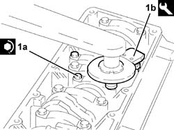
1. Tighten the bearing cap bolts (1a) to the recommended torque; use the tool (1b) for the angular tightening.
| Fastening | Component | Ø | Value (daNm) | |
|---|---|---|---|---|
| 1a | Bolt | BIG END BEARING CAPS | M9 | 2.0 + 60° |
| Name | Country | |
|---|---|---|
| 1b | Protractor | 1.860.942.000 |
1. Fit the tool.
| Name | Country | |
|---|---|---|
| 1 | Flange | 1.820.618.000 |
Rotate the crankshaft using the tool fitted previously until the cylinder concerned is at B.D.C.
2. Undo the bolts (2a) and remove the big end bearing cap (2b).
3. Remove the lower big end bearing shell.
4. Remove the connecting rod-piston assembly.
5. Remove the upper big end bearing shell.
Proceed in the same way with the removal of the pistons and connecting rods for the remaining cylinders.
Remove the tool for rotating the crankshaft.
| Name | Country | |
|---|---|---|
| Flange | 1.860.815.000 |
Fit the intake on the oil pump.
Fit the flywheel lock.
| Name | Country | |
|---|---|---|
| 1 | Counter-torque | 1.860.846.000 |
Fit the two bolts removed previously fixing the flywheel and tighten them to the recommended torque.
| Fastening | Component | Ø | Value (daNm) | |
|---|---|---|---|---|
| 2c | Bolt | FLYWHEEL | M8 | 4.4 |
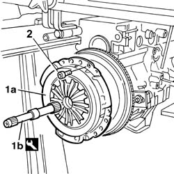
1. Line up the driven plate for fitting the clutch assembly (1a), using the centring pin (1b).
| Name | Country | |
|---|---|---|
| 1b | Clutch centering | 1.870.418.000 |
2. Tighten the bolts fixing the clutch to the engine flywheel.
Remove the engine flywheel lock applied previously.
Remove the tool for rotating the crankshaft.
| Name | Country | |
|---|---|---|
| Flange | 1.860.815.000 |
Fit the intake on the oil pump.
Fit the flywheel lock.
| Name | Country | |
|---|---|---|
| Counter-torque | 1.860.846.000 |
Fit the two bolts removed previously fixing the flywheel and tighten them to the recommended torque.
| Fastening | Component | Ø | Value (daNm) | |
|---|---|---|---|---|
| Bolt | FLYWHEEL | M8 | 4.4 |
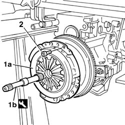
1. Line up the driven plate for fitting the clutch assembly (1a), using the centring pin (1b).
| Name | Country | |
|---|---|---|
| 1b | Clutch centering | 1.870.418.000 |
2. Tighten the bolts fixing the clutch to the engine flywheel.
Remove the engine flywheel lock applied previously.
Fit the connecting rod caps.
Tighten the nuts fixing the connecting rod caps to torque.
| Fastening | Component | Ø | Value (daNm) | |
|---|---|---|---|---|
| Nut | BIG END BEARING CAPS | M9 | 4.8 - 5.4 |
Remove the tool for rotating the crankshaft.
| Name | Country | |
|---|---|---|
| Flange | 1.860.815.000 |
Fit the section of the engine oil dipstick inside the cylinder block/crankcase.
Position a new oil pump gasket.
Fit the oil pump tightening the fixing bolts to torque.
| Fastening | Component | Ø | Value (daNm) | |
|---|---|---|---|---|
| Bolt | ENGINE OIL PUMP | M8 | 2.3 ÷ 2.8 |
- 1020A24 crank case oil sump - r + r clean seals for sealant application with engine removed.
Remove the tool.
| Name | Country | |
|---|---|---|
| Flange | 1.860.815.000 |
Fit the engine oil inlet complete with gasket and secure using the bolts.
Apply the recommended sealant to the entire perimeter of the crankcase sump.
| Type | Component | Name | Qty. | |
|---|---|---|---|---|
| Silicon sealant | OIL SUMP | Dow Corning 7091 |
Fit the crankcase sump.
Tighten the side bolts for the crankcase sump to torque using the tool.
| Fastening | Component | Ø | Value (daNm) | |
|---|---|---|---|---|
| Side bolt | OIL SUMP | M6 | (Engine block side) 0.9 ÷ 1.2 |
| Name | Country | |
|---|---|---|
| Key | 1.860.833.000 |
Tighten the front and rear bolts for the crankcase sump to torque using the tool.
| Fastening | Component | Ø | Value (daNm) | |
|---|---|---|---|---|
| Front and rear bolt | OIL SUMP | M8 | (Engine crankcase side) 2.3 ÷ 3.3 |
| Name | Country | |
|---|---|---|
| Key | 1.860.834.000 |
Tighten the bolt securing the oil sump to the intermediate shaft support.
Refitting
1. Refit the piston - connecting rod assembly (1a), complete with half-bearing, using the tool (1b).
To select the connecting rod half-bearings, follow the procedure described previously for the main journal half-bearings - 1004E20 engine - dismantle and re-build following operation 1004e10 - wash and check dismantled parts - re-fit cylinder head and oil sump - does not include repairs to cylinder head and auxiliary unit.
The piston - connecting rod assemblies are fitted in the cylinder block/crankcase so that the discharge on the piston skirt is in line with the oil jet fitted on the cylinder block/crankcase.
Proceed in the same way with the refitting of the pistons and connecting rods for the remaining cylinders.
- 1020A24 crank case oil sump - r + r clean seals for sealant application with engine removed.
- 1020A24 crank case oil sump - r + r clean seals for sealant application with engine removed
1. Check the clearance of the connecting rod bearings, using the calibrated wire (Plastigage).
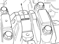
Place the big end caps complete with half-bearings back in their housings.
The connecting rod caps are fitted so that the number stamped on them is facing the same side as the one stamped on the big end (inlet side).
1. Tighten bolts (1a) to the recommended torque using angular tightening tool (1b).
| Fastening | Component | Ø | Value (daNm) | |
|---|---|---|---|---|
| 1a |
| Name | Country | |
|---|---|---|
| 1b | Protractor | 1.860.942.000 |
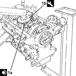
Undo the nuts and remove the connecting rod caps complete with half-bearings fitted previously.
1. Using a suitable graduate measuring instrument (1a), measure the clearance shown by the calibrated wire (1b).
| Measurement | Value | ||
|---|---|---|---|
| 1b | Clearance between big end bearings-Crankpins (mm) | 0.016 ÷ 0.070 |
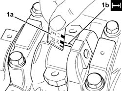
If the value measured does not correspond to the recommended figures, replace the connecting rod bearings.
Carry out this check on all the connecting rod bearings, one at a time, without rotating the crankshaft.
Place the connecting rod cap, complete with half-bearing, back in its housing and fix it using the bolts without tightening them.
The connecting rod caps are fitted so that the number stamped on them is facing the same side as the one stamped on the big end (inlet side).
1. Tighten the bolts (1a) for the connecting rod caps to the recommended torque, using the angular tightening tool (1b).
| Fastening | Component | Ø | Value (daNm) | |
|---|---|---|---|---|
| 1a |
| Name | Country | |
|---|---|---|
| 1b | Protractor | 1.860.942.000 |
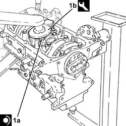
Remove the tool.
| Name | Country | |
|---|---|---|
| Flange | 1.820.618.000 |
Place the engine oil intake, complete with gasket, back in its housing and secure it using the bolts.
Apply silicon sealant around the edge of the crankcase sump.
1. Refit the crankcase sump
2. Tighten the side bolts (2a) for the crankcase sump to the recommended torque using the tool (2b).
| Fastening | Component | Ø | Value (daNm) | |
|---|---|---|---|---|
| 2a |
| Name | Country | |
|---|---|---|
| 2b | Spanner | 1.860.833.001 |
3. Tighten the front and rear bolts (3a) for the crankcase sump to the recommended torque using the tool (3b).
| Fastening | Component | Ø | Value (daNm) | |
|---|---|---|---|---|
| 3a |
| Name | Country | |
|---|---|---|
| 3b | Spanner | 1.860.834.001 |
Place the engine flywheel protection back in its housing and secure it using the bolts.
1. Fit the flywheel lock.
| Name | Country | |
|---|---|---|
| 1 | Counter-torque | 1.860.846.001 |
2. Refit the engine flywheel (2a) and secure by tightening new sealant-treated bolts (2b) to the recommended torque.
| Fastening | Component | Ø | Value (daNm) | |
|---|---|---|---|---|
| 2b |
Use the tool for angular tightening of the engine flywheelbolts.
| Name | Country | |
|---|---|---|
| Protractor | 1.860.942.000 |
Remove the flywheel lock.
| Name | Country | |
|---|---|---|
| Counter-torque | 1.860.846.001 |
Parts & tools for this job For 2001 Fiat Stilo
- PARTEngine gasket setSearch: Fiat Stilo 2001 engine gasket set
- TOOLTorque wrenchSearch: 3/8 inch torque wrench
- TOOLFeeler gauge setSearch: feeler gauge set
Links open Amazon search results in a new tab. As an Amazon Associate I earn from qualifying purchases.