
Piston connecting rod set - r r
- Make
- Fiat
- Model
- Stilo Factory Service Manual
- Year
- 2001–2007
- Section
- Pistons and connecting rods › Piston connecting rod set - r r
Piston connecting rod set - r r
Removing
- 1028H21 piston with connecting rod - r r.
Extend the operation to all power unit pistons and connecting rods.
Removing
Place the vehicle on a ramp.
- 1016A10 sound-proofing cover - r + r
- 5530B56 BATTERY DRIP TRAY COVER - R.R.
Disconnect the battery negative terminal.
| Name | Connector | |
|---|---|---|
| Battery | A1 |
- 7055B54 under-engine guard - r r
- 7055B42 Additional FRONT WHEEL ARCH (one), left or right - R.R. (Right side).
- 4450B10 Front WHEEL (one) - R.R. (Right side).
1. Disconnect the lower coolant inlet hose from the radiator, radiator side.
To disconnect the hose, press the clips manually and remove the rapid attachment.
Collect the coolant in a suitable container.
- 1092D10 air conditioner compressor drive belt - r + r
- 1092B60 alternator drive belt - r + r
- 1008B10 power unit front mount (timing side) flexible block - replace
- 1008A46 cam shaft left rigid mount - r r
- 1032D12 timing system protective cover(s) - r + r
- 1092A10 Crankshaft services PULLEY - R.R.
- 1056B82 injection/ignition system e.c.u. (one) - r + r
- 1056B87 ignition/injection system control unit mount - r r
- 1036G49 rear camshaft seal, lh or rh - r r with mount and coil/s removed
- 1032B10 toothed timing belt - r + r for timing adjustment or replacement
- 1048A32 sleeve from air cleaner to intake manifold - r + r
- 1056B15 throttle body intergral with mds - r r
- 1084A16 oil dip stick pipe - r r
- 1084A22 engine oil filler - r r
- 1072B50 sleeves connecting air capacity box to inlet manifold is - r+r
- 1032B40 toothed-driven pulley (one) - r + r with timing belt removed
- 1072B14 inlet manifold - r+r and replace seal with air conveyor/box removed
- 1080B94 front lambda probe with catalitic converter r r
- 1072C44 exhaust manifold heat shield on bulkhead - r+r
- 1072C16 exhaust manifold with catalytic converter - r r
- 1016B26 rh cylinder head extension -r r with timing belt removed -replace gasket
- 1016B22 lh cylinder head extension - r r with timing belt removed - replace gasket
- 1088C30 thermostat unit - r+r
- 1016C10 cylinder head - r + r and replace gasket
- 1020A20 crank case oil sump - r + r clean seals for sealant application
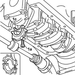
1. Undo the bolts (1a) and remove the connecting rod caps (1b) for cylinders 1 and 4 complete with lower connecting rod bearing halves.
Removing
Place the car on a ramp.
- 1016A40 ignition coil cover on cylinder head- r+r
- 5530B56 BATTERY DRIP TRAY COVER - R.R.
Disconnect the battery negative terminal.
- 1048A28 vacuum air circuit resonator pipe - r+r
- 1048A32 sleeve from air cleaner to intake manifold - r + r
- 1048A23 cold air intake - r r
- 4450B10 Front WHEEL (one) - R.R.
- 7055B54 under-engine guard - r r
- 7055B42 Additional FRONT WHEEL ARCH (one), left or right - R.R.
- 1088B10 engine cooling tank - r + r
- 5510C14 ignition coil/s - r+r
- 1016A20 single cam cover - r + r and replace gasket
- 1008A46 cam shaft left rigid mount - r r
- 1032D12 timing system protective cover(s) - r + r
- 1016B12 single cylinder head extension - r r with timing belt removed - replace
- 1076B50 exhaust pipe attachment to engine - r + r
Rotate the crankshaft so that cylinder no. 1 is at BDC.
1. Undo the bolts (1a) and remove the connecting rod caps (1b) for cylinders 1 and 4 complete with lower connecting rod bearing halves.
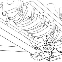
This operation should be carried out with the engine at the bench. After having remove the power unit, separate the gearbox - differential unit from the engine and position the latter on the rotating stand for overhauling.
Remove the pistons, referring to the operations illustrated in the manual for overhauling this engine at the bench.
Refitting
Fit the pistons in increasing order starting from the timing side. The arrow on the piston crown must be turned toward the camshaft side.
- 1028H21 piston with connecting rod - r r.
Extend the operation to all power unit pistons and connecting rods.
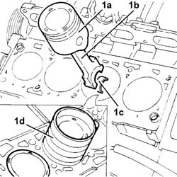
1. Withdraw and remove pistons (1a) with connecting rods (1b) and cylinder 1 and 4 upper connecting rod bearing halves (1c).
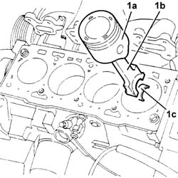
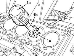
1. Withdraw and remove pistons (1a) with connecting rods (1b) and cylinder 1 and 4 upper connecting rod bearing halves (1c).
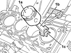
Follow the same procedure to remove the connecting rod-piston assemblies for cylinders no. 2 and no. 3.
Follow the same procedure to remove the connecting rod-piston assemblies for cylinders no. 2 and no. 3 rotating the crankshaft through 180 degrees.
Refitting
1. Fit cylinder 2 and 3 pistons (1a), connecting rods (1b) and upper connecting rod bearing shells using a suitable fitting tool (1d).
Fit the connecting rod - piston assembly in the cylinder block so that the arrow (indicating engine rotation direction) stamped near the small end or piston crown is facing the inlet side.
Refitting
1. Fit cylinder 2 and 3 pistons (1a), connecting rods (1b) and upper connecting rod bearing shells using a suitable fitting tool.
Fit the connecting rod - piston assembly in the crankcase with the large grooves (for the inlet valves) on the piston crowns facing towards the inlet side.
Fit the connecting rod caps of the 2nd and 3rd cylinders, complete with half-bearings, and secure by tightening the bolts to the recommended torque.
The connecting rod caps are fitted so that the number stamped on them is facing the same side as the one stamped on the big end (inlet side).
| Fastening | Component | Ø | Value (daNm) | |
|---|---|---|---|---|
| 1c | Bolt | BIG END BEARING CAPS | M9 | 4.8 - 5.4 |
Proceed in the same way to fit cylinder 1 and 4 pistons and connecting rods.
- 1020A20 crank case oil sump - r + r clean seals for sealant application
- 1016C10 cylinder head - r + r and replace gasket
- 1088C30 thermostat unit - r+r
- 1016B22 lh cylinder head extension - r r with timing belt removed - replace gasket
- 1016B26 rh cylinder head extension -r r with timing belt removed -replace gasket
- 1072C16 exhaust manifold with catalytic converter - r r
- 1072C44 exhaust manifold heat shield on bulkhead - r+r
- 1080B94 front lambda probe with catalitic converter r r
- 1072B14 inlet manifold - r+r and replace seal with air conveyor/box removed
- 1032B40 toothed-driven pulley (one) - r + r with timing belt removed
- 1072B50 sleeves connecting air capacity box to inlet manifold is - r+r
- 1084A22 engine oil filler - r r
- 1084A16 oil dip stick pipe - r r
- 1056B15 throttle body intergral with mds - r r
- 1048A32 sleeve from air cleaner to intake manifold - r + r
- 1032B10 toothed timing belt - r + r for timing adjustment or replacement
- 1036G49 rear camshaft seal, lh or rh - r r with mount and coil/s removed
- 1056B87 ignition/injection system control unit mount - r r
- 1056B82 injection/ignition system e.c.u. (one) - r + r
- 1092A10 Crankshaft services PULLEY - R.R.
- 1032D12 timing system protective cover(s) - r + r
- 1008A46 cam shaft left rigid mount - r r
- 1008B10 power unit front mount (timing side) flexible block - replace
- 1092B60 alternator drive belt - r + r
- 1092B64 alternator drive belt - adjust tension
- 1092D10 air conditioner compressor drive belt - r + r
Connect the lower coolant outlet hose from the radiator, radiator side.
- 4450B10 Front WHEEL (one) - R.R. (Right side).
- 7055B42 Additional FRONT WHEEL ARCH (one), left or right - R.R. (Right side).
- 7055B54 under-engine guard - r r
Connect the battery's negative terminal.
| Name | Connector | |
|---|---|---|
| Battery | A1 |
- 5530B56 BATTERY DRIP TRAY COVER - R.R.
- 1016A10 sound-proofing cover - r + r
| Type | Component | Name | Qty. | |
|---|---|---|---|---|
| Fluid | CYLINDER HEAD | Paraflu 11 |
Remove the car from the ramp.
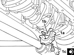
1. Fit the cylinder 2 and 3 connecting rod caps (1a), complete with half-bearings (1b), and secure by tightening the bolts (1c) to the recommended torque using a suitable tool for the angular rotation.
The connecting rod caps are fitted so that the number stamped on them is facing the same side as the one stamped on the big end (inlet side).
| Name | Country | |
|---|---|---|
| Protractor | 1.860.942.000 |
| Fastening | Component | Ø | Value (daNm) | |
|---|---|---|---|---|
| 1c | Bolt | BIG END BEARING CAPS | M9 | 2.5 + 60° |
- 1076B50 exhaust pipe attachment to engine - r + r
- 1016C10 cylinder head - r + r and replace gasket
- 1032D12 timing system protective cover(s) - r + r
- 1008A46 cam shaft left rigid mount - r r
- 1016A20 single cam cover - r + r and replace gasket
- 5510C14 ignition coil/s - r+r
- 1088B10 engine cooling tank - r + r
- 7055B42 Additional FRONT WHEEL ARCH (one), left or right - R.R.
- 7055B54 under-engine guard - r r
- 4450B10 Front WHEEL (one) - R.R.
- 1048A23 cold air intake - r r
- 1048A32 sleeve from air cleaner to intake manifold - r + r
- 1048A28 vacuum air circuit resonator pipe - r+r
Connect the battery negative terminal.
- 5530B56 BATTERY DRIP TRAY COVER - R.R.
- 1016A40 ignition coil cover on cylinder head- r+r
- 0010T21 coolant check density and top up if necessary
Remove the vehicle from the ramp.
Parts & tools for this job For 2001 Fiat Stilo
- PARTEngine gasket setSearch: Fiat Stilo 2001 engine gasket set
- TOOLTorque wrenchSearch: 3/8 inch torque wrench
- TOOLFeeler gauge setSearch: feeler gauge set
Links open Amazon search results in a new tab. As an Amazon Associate I earn from qualifying purchases.