
Cylinder head - r + r and replace gasket
- Make
- Fiat
- Model
- Stilo Factory Service Manual
- Year
- 2001–2007
- Section
- Cylinder head/s › Cylinder head - r + r and replace gasket
Cylinder head - r + r and replace gasket
Removing
Place the vehicle on a ramp.
- 1016A10 sound-proofing cover - r + r
- 5530B56 BATTERY DRIP TRAY COVER - R.R.
Disconnect the battery negative terminal.
| Name | Connector | |
|---|---|---|
| Battery | A1 |
- 7055B54 under-engine guard - r r
- 7055B42 Additional FRONT WHEEL ARCH (one), left or right - R.R.
- 4450B10 Front WHEEL (one) - R.R.
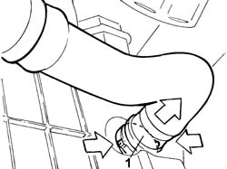
1. Disconnect the lower coolant inlet hose from the radiator, radiator side.
To disconnect the hose, press the springs manually and remove the rapid attachment.
Collect the coolant in a suitable container.
Removing
Place the car on a ramp.
- 1016A40 ignition coil cover on cylinder head- r+r
- 5530B56 BATTERY DRIP TRAY COVER - R.R.
Disconnect the positive battery terminal.
- 1048A28 vacuum air circuit resonator pipe - r+r
- 1048A32 sleeve from air cleaner to intake manifold - r + r
- 1048A23 cold air intake - r r
- 4450B10 Front WHEEL (one) - R.R.
- 7055B54 under-engine guard - r r
- 7055B42 Additional FRONT WHEEL ARCH (one), left or right - R.R.
Lower the ramp.
- 1088B10 engine cooling tank - r + r
- 5510C14 ignition coil/s - r+r
- 1016A20 single cam cover - r + r and replace gasket
Raise the lift.
- 1008A46 cam shaft left rigid mount - r r
- 1032D12 timing system protective cover(s) - r + r
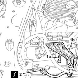
1. Undo the bolts (1a) fixing the reinforcement bracket (1b).
2. Disconnect the electrical connection for the rpm sensor.
| Name | Connector | |
|---|---|---|
| 2 | RPM sensor | K46 |
Removing
Place the car on a lift.
- 7055B54 under-engine guard - r r.
Position a suitable container to collect the coolant.
Disconnect the lower radiator hose.
- 1016A40 ignition coil cover on cylinder head- r+r
- 5530B56 BATTERY DRIP TRAY COVER - R.R.
Disconnect the battery negative terminal.
- 5530B52 Battery DRIP TRAY/SUPPORT - R.R.
- 1056B82 injection/ignition system e.c.u. (one) - r + r
- 1056B14 throttle case - r + r
- 1072B10 inlet manifold - r + r and replace seal
- 1072D50 device (vis) with adjustable air ducts - r r
- 1088E10 radiator cooling fan - r + r
- 1072C44 exhaust manifold heat shield on bulkhead - r+r
- 1072C10 exhaust manifold - r + r and replace seal
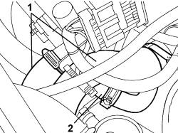
1. Disconnect the lower pipe and the upper pipe from the thermostat.
2. Disconnect the pipes from the rigid pipe.
Disconnect the supply and return pipes.
- 1092B50 alternator/air conditioner compressor drive belt - adjust tension
- 1008B10 power unit front mount (timing side) flexible block - replace
- 1008A46 cam shaft left rigid mount - r r
- 1032D12 timing system protective cover(s) - r + r
- 1092A10 Crankshaft services PULLEY - R.R.
- 1056B82 injection/ignition system e.c.u. (one) - r + r
- 1056B87 ignition/injection system control unit mount - r r
- 1036G49 rear camshaft seal, lh or rh - r r with mount and coil/s removed
- 1032B10 toothed timing belt - r + r for timing adjustment or replacement
- 1048A32 sleeve from air cleaner to intake manifold - r + r
- 1056B15 throttle body intergral with mds - r r
- 1084A16 oil dip stick pipe - r r
- 1084A22 engine oil filler - r r
- 1072B50 sleeves connecting air capacity box to inlet manifold is - r+r
- 1032B40 toothed-driven pulley (one) - r + r with timing belt removed
- 1072B14 inlet manifold - r+r and replace seal with air conveyor/box removed
- 1080B94 front lambda probe with catalitic converter r r
- 1072C44 exhaust manifold heat shield on bulkhead - r+r
- 1072C16 exhaust manifold with catalytic converter - r r
- 1016B26 rh cylinder head extension -r r with timing belt removed -replace gasket
- 1016B22 lh cylinder head extension - r r with timing belt removed - replace gasket
- 1088C30 thermostat unit - r+r
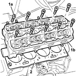
1. Undo the bolts (1a) and remove the cylinder head (1b).
2. Remove the cylinder head gasket.
Lower the vehicle.
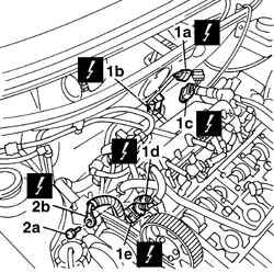
1. Disconnect the electrical connections (1a), (1b), (1c), (1d) and (1e).
| Name | Connector | |
|---|---|---|
| 1a | Lambda sensor downstream of post-catalyzer | K17 |
| Name | Connector | |
|---|---|---|
| 1b | Engine management ECU | M10 |
| Name | Connector | |
|---|---|---|
| 1c | Engine coupling/ i.e. | D24 |
| Name | Connector | |
|---|---|---|
| 1d | Detonation sensor | K50 |
| Name | Connector | |
|---|---|---|
| 1e | Timing sensor | K47 |
2. Undo the fixing bolt (2a) and disconnect the earth lead (2b) from the timing tensioners support.
| Name | Connector | |
|---|---|---|
| 2b | Earth on engine | C40 |
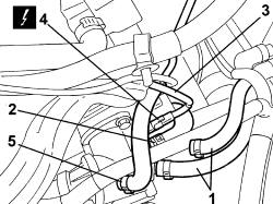
1. Disconnect the heater supply and return pipes.
2. Disconnect the supply pipe from the water pump.
3. Disconnect the earth lead from the cylinder head.
4. Disconnect the electrical connection from the engine coolant temperature sensor.
| Name | Connector | |
|---|---|---|
| 4 | Engine temperature sender unit | K36 |
5. Disconnect the recirculation pipe from the connector on the thermostat.
Refitting
Clean the cylinder head and crankcase contact surfaces.
Fit a new cylinder head gasket so that the wording 'ALTO [TOP] printed on the gasket is turned toward the operator.
The cylinder head gasket is of the Astadur type. The material from which these gaskets are made undergoes a polymerization process during the operation of the engine so that they become considerably harder during usage. In order for the polymerization of the gasket to take place it is necessary to:
- keep the gasket in its sealed container until fitting
- not lubricate or get oil on the gasket and the contact surfaces.
Refit the cylinder head.
Fit all the cylinder head bolts.
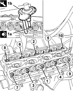
1. Tighten the bolts (1a) fixing the cylinder head to the recommended torque using the angular tightening tool (1b).
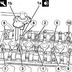
Follow the tightening order shown in the figure during the different stages.
| Fastening | Component | Ø | Value (daNm) | |
|---|---|---|---|---|
| 1a | Bolt | CYLINDER HEAD | M10 | 4 + 90° + 90° |
| Name | Country | |
|---|---|---|
| 1b | Protractor | 1.860.942.000 |
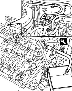
1. Fit fuel presure outlet device onto fuel manifold.
| Name | Country | |
|---|---|---|
| 1 | Rapid connector | 1.870.684.000 |
2. Disconnect the fuel supply pipe from the fuel manifold.
3. Disconnect the anti-evaporation system pipe from the rapid attachment.
1. Disconnect the engine coolant pipe from the reservoir to the water pump rigid inlet pipe.
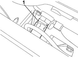
- 1088C30 thermostat unit - r+r
- 1016B22 lh cylinder head extension - r r with timing belt removed - replace gasket
- 1016B26 rh cylinder head extension -r r with timing belt removed -replace gasket
- 1072C16 exhaust manifold with catalytic converter - r r
- 1072C44 exhaust manifold heat shield on bulkhead - r+r
- 1080B94 front lambda probe with catalitic converter r r
- 1072B14 inlet manifold - r+r and replace seal with air conveyor/box removed
- 1032B40 toothed-driven pulley (one) - r + r with timing belt removed
- 1072B50 sleeves connecting air capacity box to inlet manifold is - r+r
- 1084A22 engine oil filler - r r
- 1084A16 oil dip stick pipe - r r
- 1056B15 throttle body intergral with mds - r r
- 1048A32 sleeve from air cleaner to intake manifold - r + r
- 1032B10 toothed timing belt - r + r for timing adjustment or replacement
- 1036G49 rear camshaft seal, lh or rh - r r with mount and coil/s removed
- 1056B87 ignition/injection system control unit mount - r r
- 1056B82 injection/ignition system e.c.u. (one) - r + r
- 1092A10 Crankshaft services PULLEY - R.R.
- 1032D12 timing system protective cover(s) - r + r
- 1008A46 cam shaft left rigid mount - r r
- 1008B10 power unit front mount (timing side) flexible block - replace
- 1092B50 alternator/air conditioner compressor drive belt - adjust tension
- 1092B54 alternator/water pump drive belt - adjust tension
Connect the lower coolant outlet hose from the radiator, radiator side.
- 4450B10 Front WHEEL (one) - R.R.
- 7055B42 Additional FRONT WHEEL ARCH (one), left or right - R.R.
- 7055B54 under-engine guard - r r
Connect the battery's negative terminal.
| Name | Connector | |
|---|---|---|
| Battery | A1 |
- 5530B56 BATTERY DRIP TRAY COVER - R.R.
- 1016A10 sound-proofing cover - r + r
| Type | Component | Name | Qty. | |
|---|---|---|---|---|
| Fluid | CYLINDER HEAD | Paraflu 11 |
Remove the car from the ramp.
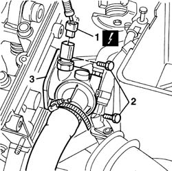
1. Disconnect the electrical connection for the temperature sensor on the thermostat.
| Name | Connector | |
|---|---|---|
| 1 | Engine temperature sender unit | K36 |
2. Undo the retaining bolts.
3. Separate the thermostat from the housing in the cylinder head.
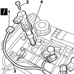
1. Disconnect the electrical connections from the ignition coils.
| Name | Connector | |
|---|---|---|
| 1 | Ignition coil | A30 |
| Name | Connector | |
|---|---|---|
| 1 | Data not available yet |
| Name | Connector | |
|---|---|---|
| 1 | Ignition coil | A30B |
| Name | Connector | |
|---|---|---|
| 1 | Ignition coil | A30C |
| Name | Connector | |
|---|---|---|
| 1 | Ignition coil | A30D |
| Name | Connector | |
|---|---|---|
| 1 | Ignition coil | A30E |
2. Undo the bolts fixing the ignition coils to the tappet cover.
3. Release the electrical wiring from the securing bands.
4. Remove the ignition coils.
- 1072C44 exhaust manifold heat shield on bulkhead - r+r
- 1072C10 exhaust manifold - r + r and replace seal
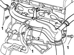
1. Unscrew the retaining bolts and nut.
2. Release the water pump rigid inlet pipe from the cylinder head.
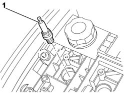
1. Remove the spark plugs underneath.
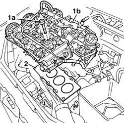
1. Undo the bolts (1a) and remove the cylinder head (1b) complete with inlet manifold.
2. Remove the cylinder head gasket.
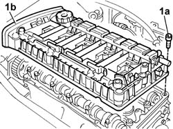
1. Undo the bolts (1a) and remove cam cover (1b), complete with seal.
Refitting
Fit a new cylinder head gasket to the cylinder block/crankcase, taking care that it is the same thickness as the old one.
ASTADUR type cylinder head gaskets are fitted.
These gaskets are made from a special material designed to undergo polymerization during the use of the engine. This means that they harden considerably during use.
To ensure the polymerisation process takes place, keep the gasket sealed in its plastic bag and do not take out until ready to fit. Do not lubricate the gasket or contaminate with oil.
Position the cylinder head on the cylinder block, taking care that the camshafts are positioned with the front cams facing outwards (valves closed).
1. Tighten the bolts (1a) fixing the cylinder head to the recommended torque using the angular tightening tool (1b).
| Fastening | Component | Ø | Value (daNm) | |
|---|---|---|---|---|
| 1a | Bolt | CYLINDER HEAD | M10 | (Engine block side) 4.0+90°+90°+90° |
| Name | Country | |
|---|---|---|
| 1b | Protractor | 1.860.942.000 |
- 4450B04 right front wheel r r
- 7055B42 Additional FRONT WHEEL ARCH (one), left or right - R.R.
- 1092D10 air conditioner compressor drive belt - r + r
- 1092B68 belt from a/c compressor to alternator drive r + r
- 1092A10 Crankshaft services PULLEY - R.R.
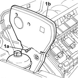
1. Using a specially shortened 5 mm socket wrench, undo the bolts fixing the shield.
2. Remove the timing belt guard.
Position the water pump rigid inlet pipe.
Tighten the nuts and bolts securing the rigid pipe to the cylinder head to torque.
| Fastening | Component | Ø | Value (daNm) | |
|---|---|---|---|---|
| Nut | COOLANT PUMP RIGID INLET PIPE | M8 | 2.5 |
| Fastening | Component | Ø | Value (daNm) | |
|---|---|---|---|---|
| Bolt | COOLANT PUMP RIGID INLET PIPE | M6 | 0.9 |
- 1072C10 exhaust manifold - r + r and replace seal
- 1072C44 exhaust manifold heat shield on bulkhead - r+r
Position the thermostat in the special housing in the cylinder head.
Tighten the bolts fixing the thermostat to torque.
| Fastening | Component | Ø | Value (daNm) | |
|---|---|---|---|---|
| Bolt | THERMOSTAT CONTAINER | M8 | 2.5 |
Connect the electrical connection to the engine coolant temperature sensor.
| Name | Connector | |
|---|---|---|
| Engine temperature sender unit | K36 |
Connect the fuel supply pipe to the fuel manifold.
Connect the anti-evaporation system pipe to the rapid attachment.
Tighten the fixing bolt and connect the earth lead to the engine.
| Name | Connector | |
|---|---|---|
| Earth on engine | C40 |
Connect the electrical connections disconnected previously.
| Name | Connector | |
|---|---|---|
| Lambda sensor downstream of post-catalyzer | K17 |
| Name | Connector | |
|---|---|---|
| Body computer | M1B |
| Name | Connector | |
|---|---|---|
| Engine coupling/ i.e. | D24 |
| Name | Connector | |
|---|---|---|
| Detonation sensor | K50 |
| Name | Connector | |
|---|---|---|
| Timing sensor | K47 |
Position the accelerator cable.
Connect the accelerator cable to the butterfly opening device and to the mounting bracket lcoking the adjustment nut.
Raise the car.
Fit the reinforcement bracket for the modular inlet manifold and tighten the fixing bolts.
Connect the electrical connection for the rpm sensor.
| Name | Connector | |
|---|---|---|
| RPM sensor | K46 |
- 1032D12 timing system protective cover(s) - r + r
- 1008A46 cam shaft left rigid mount - r r
Lower the ramp.
- 1016A20 single cam cover - r + r and replace gasket
- 5510C14 ignition coil/s - r+r
- 1088B10 engine cooling tank - r + r
Raise the lift.
- 7055B42 Additional FRONT WHEEL ARCH (one), left or right - R.R.
- 7055B54 under-engine guard - r r
- 4450B10 Front WHEEL (one) - R.R.
- 1048A23 cold air intake - r r
- 1048A32 sleeve from air cleaner to intake manifold - r + r
- 1048A28 vacuum air circuit resonator pipe - r+r
Connect the positive battery terminal.
- 5530B56 BATTERY DRIP TRAY COVER - R.R.
- 1016A40 ignition coil cover on cylinder head- r+r
- 0010T21 coolant check density and top up if necessary
Remove the vehicle from the lift.
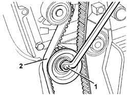
1. Undo the nut for the automatic tensioner in order to loosen the timing drive belt tension.
2. Remove the timing drive belt from the drive pullies.
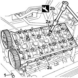
1. Undo the bolt fixing the cover behind the exhaust side timing pulley to the cylinder head.
2. Undo the bolts (2a), using the spanner (2b) and remove the cylinder head (2c).
Remove the cylinder head gasket underneath.
| Name | Country | |
|---|---|---|
| 2b | Hexagonal splined wrench | 1.852.154.000 |
Refitting
Position the cylinder head gasket on the cylinder block.
The cylinder head gasket is of the Astadur type. The material from which these gaskets are made undergoes a polymerization process during the operation of the engine so that they become considerably harder during usage. In order for the polymerization process to take place it is necessary to: keep the gasket in its sealed container until it is fitted; - not lubricate or get oil on the gasket and the contact surfaces.
Position the cylinder head on the cylinder block/crankcase, taking care that the camshafts are positioned with the front cams facing outwards (valves closed).
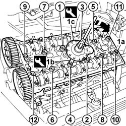
1. Tighten the bolts (1a) fixing the cylinder head, in successive stages, using the spanner (1b) for torque tightening and the spanner (1c) for angular tightening.
Follow the order shown in the diagram for each tightening sequence.
| Fastening | Component | Ø | Value (daNm) | |
|---|---|---|---|---|
| 1a | Bolt | CYLINDER HEAD | M10 | 4 + 90° + 90° |
| Name | Country | |
|---|---|---|
| 1b | Hexagonal splined wrench | 1.852.154.000 |
| Name | Country | |
|---|---|---|
| 1c | Protractor | 1.860.942.000 |
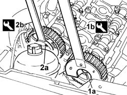
1. Undo the bolt (1a) for the timing driven pulley, exhaust side using the tools (1b) and (1c) for counter-torque.
| Name | Country | |
|---|---|---|
| 1b | Support for counter-torque | 1.860.831.000 |
| Name | Country | |
|---|---|---|
| 1c | Spanner for camshaft pulley rotation | 1.860.831.002 |
2. Slacken the bolts (2a) on the inlet side camshaft pulley, using the tool (2b) for counter-torque.
| Name | Country | |
|---|---|---|
| 2b | Counter-torque | 1.860.856.000 |
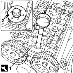
1. Fit the tool (1a), complete with dial gauge (1b), in the housing of the spark plug for cylinder no. 1.
| Name | Country | |
|---|---|---|
| 1a | Probe mount | 1.860.895.000 |
Rotate the crankshaft until the piston for cylinder no. 1 is at T.D.C. at the combustion stroke.
2. With cylinder no. 1 at T.D.C., check that the reference on the crankshaft drive gear coincides with the reference on the crankshaft front cover.
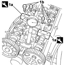
Undo the bolts and remove the third inlet side camshaft cap and the second exhaust side camshaft cap.
Mark the position of the camshaft caps following removal so that they can be positioned correctly upon refitting.
1. Fit templates (1a) in place of the camshaft caps removed and fix it tightening the bolts (1b).
Check that the camshaft cam profile matches the tool correctly.
| Name | Country | |
|---|---|---|
| 1a | Gauge | 1.870.828.000 |
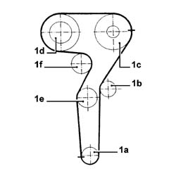
1. Fit the toothed timing belt following the order;
toothed drive pulley (1a)
fixed tensioner (1b)
exhaust side toothed driven pulley (1c)
intake side toothed driven pulley (1d)
mobile tensioner (1e)
coolant pump pulley (1f).
When fitting, ensure that the arrow stamped on the belt is facing in the direction of engine rotation. Three notches on the belt must also line up, during the initial fitting, with notches on the toothed drive pulley and on the intake and exhaust toothed driven pulleys.
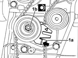
1. Using a screwdriver, apply force to the automatic tensioner tab (1a) so that the tensioner is in the maximum tension position, then tighten the nut (1b) fixing the tensioner to the support.
| Fastening | Component | Ø | Value (daNm) | |
|---|---|---|---|---|
| 1b | Nut | MOBILE TIMING TENSIONER | M8 | 2.5 |
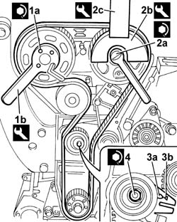
1. Tighten the bolts (1a) for the camshaft toothed driven pulley, inlet side, to the recommended torque using the tool (1b) for counter-torque.
| Fastening | Component | Ø | Value (daNm) | |
|---|---|---|---|---|
| 1a | Bolt | TIMING GEAR DRIVEN PULLEYS | M6 | (Inlet side) 0.9 |
| Name | Country | |
|---|---|---|
| 1b | Counter-torque | 1.860.856.000 |
2. Tighten the bolts (2a) for the camshaft driven pulley, exhaust side, to the recommended torque using the tools (2b) and (2c) for counter-torque.
| Fastening | Component | Ø | Value (daNm) | |
|---|---|---|---|---|
| 2a | Bolt | TIMING GEAR DRIVEN PULLEYS | M12 | (Exhaust side) 12 |
| Name | Country | |
|---|---|---|
| 2b | Support for counter-torque | 1.860.831.000 |
| Name | Country | |
|---|---|---|
| 2c | Spanner for camshaft pulley rotation | 1.860.831.002 |
Undo the fixing bolts and remove the jigs.
| Name | Country | |
|---|---|---|
| Gauge | 1.870.828.000 |
Fit the camshaft caps removed previously and tighten the bolts to torque.
| Fastening | Component | Ø | Value (daNm) | |
|---|---|---|---|---|
| Bolt | Camshaft caps | M7 | 1.5 |
Rotate the crankshaft through two revolutions in its normal direction of rotation.
Loosen the moving tensioner nut.
3. Using a screwdriver, rotate the timing moving tensioner so that the tensioner moving reference (3a) coincides with the fixed reference (3b).
4. Tighten the nut for the moving tensioner to the recommended torque.
| Fastening | Component | Ø | Value (daNm) | |
|---|---|---|---|---|
| Nut | MOBILE TIMING TENSIONER | M8 | 2.5 |
Remove the tool complete with dial gauge.
| Name | Country | |
|---|---|---|
| Probe mount | 1.860.895.000 |
Fit the spark plugs for the cylinders and tighten them to the recommended torque.
| Fastening | Component | Ø | Value (daNm) | |
|---|---|---|---|---|
| SPARK PLUGS | M14 x 1.25 | 2.7 |
Position the timing drive belt cover and secure it using the fixing bolts.
| Fastening | Component | Ø | Value (daNm) | |
|---|---|---|---|---|
| Bolt | BELT PROTECTION COVER | M6 | 0.9 |
- 1092A10 Crankshaft services PULLEY - R.R..
- 1092B68 belt from a/c compressor to alternator drive r + r
- 1092D10 air conditioner compressor drive belt - r + r
- 7055B42 Additional FRONT WHEEL ARCH (one), left or right - R.R.
- 4450B04 right front wheel r r
Position the tappet cover and secure it using the fixing bolts.
| Fastening | Component | Ø | Value (daNm) | |
|---|---|---|---|---|
| Bolt | CAM COVER | M6 | 0.9 |
Position the ignition coils and secure them using the fixing bolts.
| Fastening | Component | Ø | Value (daNm) | |
|---|---|---|---|---|
| Bolt | IGNITION COIL/REEL | M6 | 0.9 |
Connect the electrical connections to the ignition coils.
| Name | Connector | |
|---|---|---|
| Ignition coil | A30 |
| Name | Connector | |
|---|---|---|
| Data not available yet |
| Name | Connector | |
|---|---|---|
| Ignition coil | A30B |
| Name | Connector | |
|---|---|---|
| Ignition coil | A30C |
| Name | Connector | |
|---|---|---|
| Ignition coil | A30D |
| Name | Connector | |
|---|---|---|
| Ignition coil | A30E |
Connect the engine coolant pipe from the reservoir to the water pump rigid inlet pipe.
Connect the connector recirculation pipe to the thermostat.
Connect the electrical connection to the engine coolant temperature sensor.
| Name | Connector | |
|---|---|---|
| Engine temperature sender unit | K36 |
Connect the cylinder head earth lead.
Connect the supply pipe from the water pump.
Connect the supply and return pipes to the heater.
Connect the supply and return pipes.
Connect the pipes to the rigid pipe.
Connect the upper and lower pipes to the thermostat.
- 1072C10 exhaust manifold - r + r and replace seal
- 1072C44 exhaust manifold heat shield on bulkhead - r+r
- 1088E10 radiator cooling fan - r + r
- 1072D50 device (vis) with adjustable air ducts - r r
- 1072B10 inlet manifold - r + r and replace seal
- 1056B14 throttle case - r + r
- 1056B82 injection/ignition system e.c.u. (one) - r + r
- 5530B52 Battery DRIP TRAY/SUPPORT - R.R.
Connect the battery negative terminal.
- 5530B56 BATTERY DRIP TRAY COVER - R.R.
- 1016A40 ignition coil cover on cylinder head- r+r
Parts & tools for this job For 2001 Fiat Stilo
- PARTEngine gasket setSearch: Fiat Stilo 2001 engine gasket set
- TOOLTorque wrenchSearch: 3/8 inch torque wrench
- TOOLFeeler gauge setSearch: feeler gauge set
Links open Amazon search results in a new tab. As an Amazon Associate I earn from qualifying purchases.