
Single cylinder head, removed - overhaul
- Make
- Fiat
- Model
- Stilo Factory Service Manual
- Year
- 2001–2007
- Section
- Cylinder head/s › Single cylinder head, removed - overhaul
Single cylinder head, removed - overhaul
Dismantling
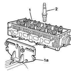
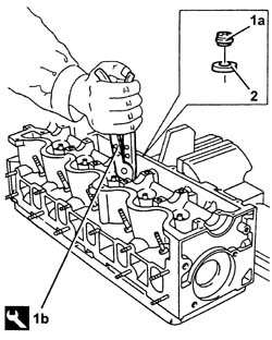
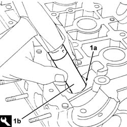
1. Position the cylinder head in the vice, supporting it with a suitable tool (1a).
2. Use a suitable wrench to remove the spark plugs
| Name | Country | |
|---|---|---|
| 1a | Support | 1.860.470.000 |
Dismantling
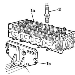
1. Position the cylinder head in the vice (1a), supporting it with a suitable tool (1b).
2. Use a suitable wrench to remove the spark plugs
| Name | Country | |
|---|---|---|
| 1b | Support | 1.860.470.000 |
Dismantling
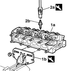
1. Position the cylinder head in the vice (1a), supporting it with a suitable tool (1b).
| Name | Country | |
|---|---|---|
| 1b | Support | 1.860.470.000 |
2. Using the tool (2a), remove the spark plugs (2b).
| Name | Country | |
|---|---|---|
| 2b | Key | 1.850.184.000 |
Dismantling
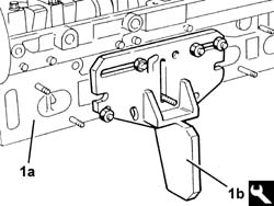
1. Position the cylinder head (1a) in the vice using the tool (1b).
| Name | Country | |
|---|---|---|
| 1b | Support | 1.860.470.000 |
Dismantling
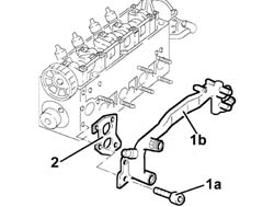
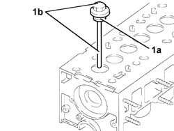
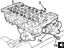
1. Undo the bolts (1a) and remove the vacuum unit (1b) complete with O-ring.
2. Undo the bolts (2a) and remove the thermostat (2b) complete with pipe and sensors.
3. Remove the gasket.
Dismantling
CAMSHAFT HOUSING
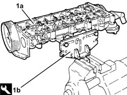
1. Position the upper cylinder head (1a) in the vice using the tool (1b).
| Name | Country | |
|---|---|---|
| 1b | Mount | 1.860.470.001 |
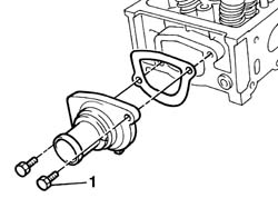
1. Remove the thermostat and the gasket underneath using the fixing bolts.
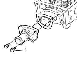
1. Remove the thermostat and the gasket underneath using the fixing bolts.
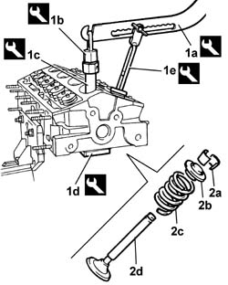
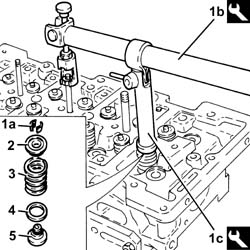
1. Using the tools (1a), (1b), (1c), (1d) and (1e) as illustrated in the diagram, compress the valve springs.
| Name | Country | |
|---|---|---|
| 1a | Lever | 1.860.790.000 |
| Name | Country | |
|---|---|---|
| 1b | Lever hook | 1.860.788.000 |
| Name | Country | |
|---|---|---|
| 1c | Extension | 1.860.787.000 |
| Name | Country | |
|---|---|---|
| 1d | Valve retaining base | 1.860.786.000 |
| Name | Country | |
|---|---|---|
| 1e | Chamber | 1.860.789.000 |
2. Remove the cotters (2a), caps (2b) and springs (2c), then remove the tool to remove the inlet and exhaust valves (2d) from the head.
Undo and remove the spark plugs.
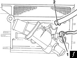
1. Disconnect the electrical connection from the engine coolant temperature sensor.
| Name | Connector | |
|---|---|---|
| 1 | Engine temperature sender unit | K36 |
2. Disconnect the coolant return pipe to the engine coolant reservoir, thermostat side.
Take the cylinder head to the workbench.
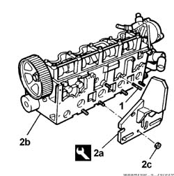
1. Undo the stud using the nut and locknut.
2. Fit tool (2a) to cylinder head (2b) and secure using nuts (2c).
| Name | Country | |
|---|---|---|
| 2a | Drift | 1.860.460.000 |
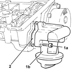
1. Undo the bolts (1a) and remove the engine oil filler (1b).
2. Remove the gasket.
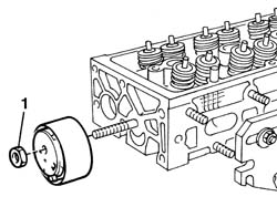
1. Undo the nut and remove the automatic timing drive belt tensioner.
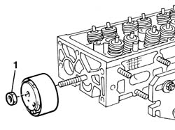
1. Undo the nut and remove the automatic timing drive belt tensioner.
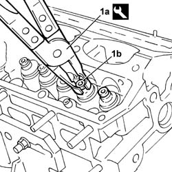
1. Using pliers (1a), remove the oil seals (1b) from the valve guides.
| Name | Country | |
|---|---|---|
| 1a | Extractor | 1.860.989.000 |
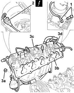
1. Disconnect the earth lead from the cylinder head.
2. Disconnect the electrical connection for the cam angle sensor.
| Name | Connector | |
|---|---|---|
| 2 | Timing sensor | K47 |
3. Undo the nuts (3a) and remove the inlet manifold (3b), complete with modular inlet manifold (3c) and butterfly casing (3d).
Remove the inlet manifold gasket.
Position the tool in the vice.
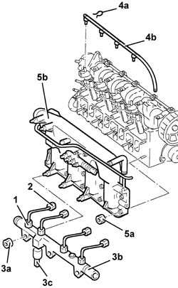
1. Loosen the manifold side connectors of the pipes leading from the fuel manifold to the injectors.
2. Undo the injector side connectors of the pipes leading from the fuel manifold to the injectors.
3. Undo the nuts (3a) and remove the fuel distributor manifold (3b), complete with pipes and fuel pressure sensor (3c).
Fully undo the connectors previously loosened and detach the pipes from fuel manifold to fuel injectors from the fuel manifold.
Use new piping from from fuel manifold to injectors upon reassembly.
4. Manually push the springs (4a) and disconnect the pipe from the injectors to the fuel recovery manifold (4b), injectors side and remove it.
Undo the nuts and disconnect the supply wiring from the heater plugs.
| Name | Connector | |
|---|---|---|
| Heater plug | A40 |
Disconnect the coolant return pipe to the expansion tank and system vent pipe from the thermostat.
5. Undo the nuts (5a) and remove the complete air intake manifold (5b).
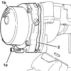
1. Undo bolts (1a) and remove vacuum unit (1b).
2. Remove the gasket.
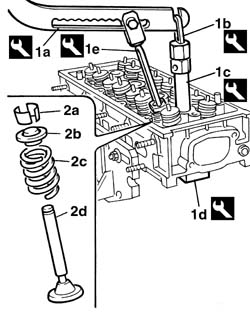
1. Using the tools (1a), (1b), (1c), (1d) and (1e) as illustrated in the diagram, compress the valve springs.
2. Remove the cotters (2a), caps (2b) and springs (2c), then remove the tool to remove the inlet and exhaust valves (2d) from the head.
| Name | Country | |
|---|---|---|
| 1a | Lever | 1.860.790.000 |
| Name | Country | |
|---|---|---|
| 1b | Lever hook | 1.860.788.000 |
| Name | Country | |
|---|---|---|
| 1c | Extension | 1.860.787.000 |
| Name | Country | |
|---|---|---|
| 1d | Valve retaining base | 1.860.786.000 |
| Name | Country | |
|---|---|---|
| 1e | Chamber | 1.860.877.000 |
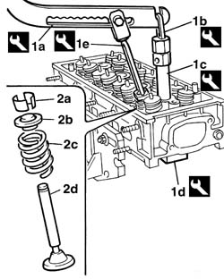
1. Using the tools (1a), (1b), (1c), (1d) and (1e) as illustrated in the diagram, compress the valve springs.
2. Remove the cotters (2a), caps (2b) and springs (2c), then remove the tool to remove the inlet and exhaust valves (2d) from the head.
| Name | Country | |
|---|---|---|
| 1a | Lever | 1.860.790.000 |
| Name | Country | |
|---|---|---|
| 1b | Lever hook | 1.860.788.000 |
| Name | Country | |
|---|---|---|
| 1c | Extension | 1.860.787.000 |
| Name | Country | |
|---|---|---|
| 1d | Valve retaining base | 1.860.786.000 |
| Name | Country | |
|---|---|---|
| 1e | Chamber | 1.860.877.000 |
Reassembling
De-carbonize and clean the valve seats and ducts.
Clean the residues of the old gasket from the lower surface of the cylinder head.
Check that the planarity of the lower cylinder head surface is within the recommended values.
| Measurement | Value | ||
|---|---|---|---|
| Flatness of bottom surface (mm) | 0.1 |
If the planarity of the cylinder head surface is not within the recommended values, regrind the head surface.
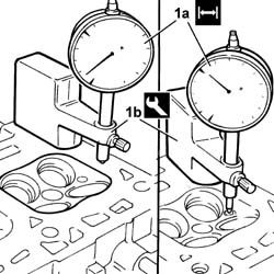
1. After regriding the cylinder head, use a dial gauge (1a) and tool (1b) to check that the minimum height between the reference plane inside the combustion chamber and the cylinder head surface is within the recommended value.
| Measurement | Value | ||
|---|---|---|---|
| 1a | Minimum height between combustion chamber plane/cylinder head (mm) | 12.5 ÷ 13.0 |
| Name | Country | |
|---|---|---|
| 1b | Dial gauge mounting | 1.870.404.000 |
The minimum permissible height after refacing is 12.5 mm.
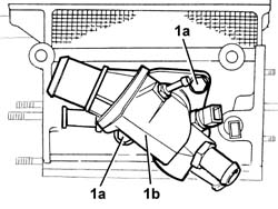
1. Undo the bolts (1a) and remove the thermostat (1b).
Remove the gasket.
Disconnect the supply pipe from the thermostat to the water return manifold to the pump, manifold side.
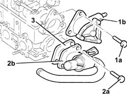
1. Undo the bolts (1a) and remove the water pump rigid inlet pipe (1b).
2. Remove the gasket.
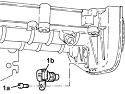
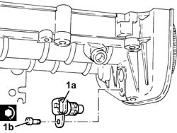
1. Undo the bolts (1a) and remove the cam angle sensor (1b).
1. Using pliers (1a), remove the oil seals (1b) from the valve guides.
2. Remove the lower valve shims.
| Name | Country | |
|---|---|---|
| 1a | Extractor | 1.860.989.000 |
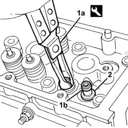
1. Using pliers (1a), remove the oil seals (1b) from the valve guides.
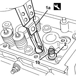
2. Remove the lower valve shims.
| Name | Country | |
|---|---|---|
| 1a | Extractor | 1.860.989.000 |
According the planarity figure measured, the cylinder head can be refaced until the minimum permissible value is reached.
If the value measured is within the tolerance, but close to the minimum permissible value, the operation of refacing the head could alter the functional characteristics of the actual cylinder head because it could cause an excessive increase in the compression ratio with consequent detonation.
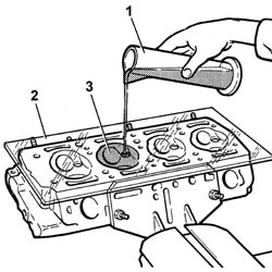
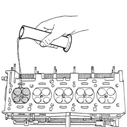
Also check the volume of all the combustion chambers following the procedure described below.
1. Temporarily fit the valves and spark plugs and use a graduated test tube containing a known quantity of engine oil.
2. Rest a glass sheet with four holes corresponding to the combustion chambers on the cylinder head.
3. Complete the filling of the combustion chamber, taking care that no oil comes out of the combustion chamber.
Wait for around 10 minutes to allow the decantation of the oil.
Measure the quantity of oil remaining in the test tube and then calculate the difference between it and the quantity of oil used initially when the test tube was full; this value corresponds to the volume of the chamber.
Check that this figure corresponds to the recommended values, or else the cylinder head has to be replaced.
| Measurement | Value | ||
|---|---|---|---|
| Volume of combustion chamber in cylinder head (cm) | 33.35 |
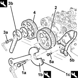
1. Undo the bolt (1a) for the timing driven pulley, exhaust side using the tools (1b) and (1c) for anti-torque.
| Name | Country | |
|---|---|---|
| 1b | Support for counter-torque | 1.860.831.000 |
| Name | Country | |
|---|---|---|
| 1c | Counter-torque | 1.860.848.000 |
2. Remove the timing driven pulley, exhaust side.
3. Undo the bolts (3a) for the inlet side camshaft pulley, using the tool (3b) for counter-torque.
| Name | Country | |
|---|---|---|
| 3b | Counter-torque | 1.860.856.000 |
4. Remove the timing driven pulley, inlet side.
5. Undo the bolts (5a) and remove the timing belt side protections (5b).
1. Undo the bolt (1a) for the driven pulley using the tools (1b).
| Name | Country | |
|---|---|---|
| 1b | Support for counter-torque | 1.860.831.000 |
| Name | Country | |
|---|---|---|
| 1b | Counter-torque | 1.860.831.001 |
2. Remove the toothed driven pulley.
3. Undo the bolts (3a) and remove the cam angle sensor (3b).
| Name | Connector | |
|---|---|---|
| 3b | Data not available yet |
4. Undo bolts (4a) and remove water pump (4b) complete with O-ring (4c).
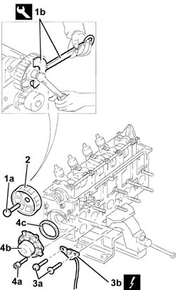
Check that the end float of the camshaft is within the recommended values using a dial gauge.
If the camshaft endfloat is not within the recommended values, when reassembling the cylinder head, replace the worn components.
1. Remove the plugs (1a) and fit the camshaft timing tools (1b) in the upper cylinder head.
Check that the tools are correctly inserted in the housings in the camshafts.
| Name | Country | |
|---|---|---|
| 1b | Gauge | 1.870.896.900 |
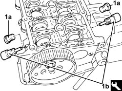
Reassembling
De-carbonize and clean the valve seats and ducts.
Clean the residues of the old gasket from the lower surface of the cylinder head.
Check that the planarity of the lower cylinder head surface is within the recommended values.
| Measurement | Value | ||
|---|---|---|---|
| Flatness of bottom surface (mm) | 0.2 |
If necessary, reface the lower cylinder head surface; it is permissible to remove 0.1 mm of material over and above the minimum cylinder head height (factory dimension).
| Measurement | Value | ||
|---|---|---|---|
| Cylinder head height (construction figure) (mm) | 77 ± 0.2 |
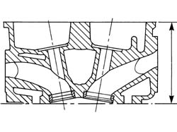
Reassembling
De-carbonize and clean the valve seats and ducts.
Clean the residues of the old gasket from the lower surface of the cylinder head.
Check that the planarity of the lower cylinder head surface is within the recommended values.
| Measurement | Value | ||
|---|---|---|---|
| Flatness of bottom surface (mm) | 0.1 |
If necessary, reface the lower cylinder head surface; it is permissible to remove 0.1 mm of material over and above the minimum cylinder head height (factory dimension).
| Measurement | Value | ||
|---|---|---|---|
| Cylinder head height (construction figure) (mm) | 77 ± 0.2 |
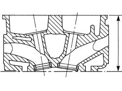
Remove the combustion residues from the valves.
Check that the valves do not show signs of scoring or seizing.
Check that the thickness of the part in contact with the valve seat is within the recommended values.
| Measurement | Value | ||
|---|---|---|---|
| Valve thickness (mm) | /= 1 |
Check that the diameter of the valve stems is within the recommended values; if this is not the case, replace the valves.
| Measurement | Value | ||
|---|---|---|---|
| Inlet valve stem diameter (mm) | 6.982 - 7.000 |
| Measurement | Value | ||
|---|---|---|---|
| Exhaust valve stem diameter (mm) | 6.974 - 6.992 |
Check that the diameter of the valve head is within the recommended values; if this is not the case, replace the valves.
| Measurement | Value | ||
|---|---|---|---|
| Diameter of inlet valve head (mm) | 30.200 - 34.500 |
| Measurement | Value | ||
|---|---|---|---|
| Diameter of exhaust valve head (mm) | 29.750 - 30.050 |
Check that the contact angle with the valve seat for both valves is within the recommended values or else the valve has to be replaced.
| Measurement | Value | ||
|---|---|---|---|
| Contact band angle with valve seat (-) | Inlet | 45° 30' +/- 5' |
| Measurement | Value | ||
|---|---|---|---|
| Contact band angle with exhaust valve seat (-) | 45° 30' +/- 5' |
Using a special instrument, check that the valve spring specifications in the various load conditions have not changed; otherwise they must be replaced.
| Measurement | Value | ||
|---|---|---|---|
| Inlet spring height (mm) | 34 | ||
| Under load (daN) | 27.8 ÷ 30.8 | ||
| Measurement | Value | ||
|---|---|---|---|
| Inlet spring height (mm) | 25.5 | ||
| Under load (daN) | 60.1 ÷ 65.9 | ||
| Measurement | Value | ||
|---|---|---|---|
| Exhaust spring height (mm) | 34 | ||
| Under load (daN) | 27.8 ÷ 30.8 | ||
| Measurement | Value | ||
|---|---|---|---|
| Exhaust spring height (mm) | 26 | ||
| Under load (daN) | 57.7 ÷ 63.5 | ||
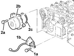
1. Undo the bolts (1a) and remove the cam angle sensor (1b).
2. Undo the bolts (2a) and remove the water pump (2b) complete with O-ring (2c).
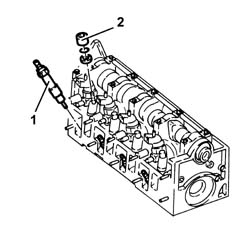
1. Undo and remove the heater plugs.
2. Undo the nuts on the brackets securing the fuel injectors with their wiashers.
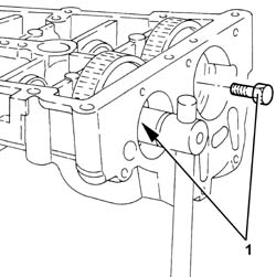
1. Undo the camshaft sprocket fixing bolts.
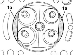
1. Check that the levelling operation has not changed any combustion chamber in areas (1a). Otherwise replace the head.
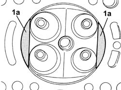
1. Check that the levelling operation has not changed any combustion chamber in areas (1a). Otherwise replace the head.
| Measurement | Value | ||
|---|---|---|---|
| Valve spring height (mm) | 34.6 | ||
| Under load (daN) | 25.0 ÷ 28.0 | ||
| Measurement | Value | ||
|---|---|---|---|
| Valve spring height (mm) | 26.0 | ||
| Under load (daN) | 59.2 ÷ 65.0 | ||
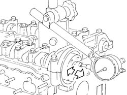
Check that the camshaft end float is within the recommended values using a dial gauge on a magnetic base.
| Measurement | Value | ||
|---|---|---|---|
| End float (mm) | 0.10 - 0.23 |
If the camshaft endfloat is not within the recommended values, when reassembling the cylinder head, replace the worn components.
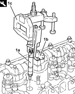
1. Remove the injectors (1a), complete with gaskets and mounting brackets (1b), using the tool (1c).
| Name | Country | |
|---|---|---|
| 1c | Extractor | 1.870.739.000 |
Remove the injector bracket support pads.
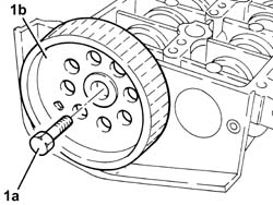
1. Undo the bolt (1a) and remove the exhaust side camshaft toothed drive pulley (1b).
Also check all the combustion chambers following the procedure described below.
- Fit valves and spark plugs provisionally. Take a graduated burette containing a known amount of engine oil.
- Rest a glass sheet with four holes corresponding to the combustion chambers on the cylinder head.
- Complete the filling of the combustion chamber, taking care that no oil comes out of the combustion chamber.
Wait for around 10 minutes to allow the decantation of the oil.
Measure the quantity of oil remaining in the burette and then calculate the difference between it and the quantity of oil used initially when the burette was full; this value corresponds to the volume of the chamber.
Check that this figure corresponds to the recommended values, or else the cylinder head has to be replaced.
| Measurement | Value | ||
|---|---|---|---|
| Combustion chamber volume (cm) | 12.28 |
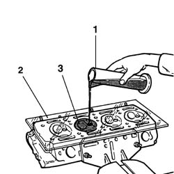
Also check all the combustion chambers following the procedure described below.
1. Fit valves and spark plugs provisionally. Take a graduated burette containing a known amount of engine oil.
2. Rest a glass sheet with four holes corresponding to the combustion chambers on the cylinder head.
3. Complete the filling of the combustion chamber, taking care that no oil comes out of the combustion chamber.
Wait for around 10 minutes to allow the decantation of the oil.
Measure the quantity of oil remaining in the burette and then calculate the difference between it and the quantity of oil used initially when the burette was full; this value corresponds to the volume of the chamber.
Check that this figure corresponds to the recommended values, or else the cylinder head has to be replaced.
| Measurement | Value | ||
|---|---|---|---|
| Combustion chamber volume (cm) | 12.28 |
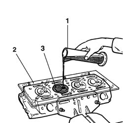
Regrind the valve seats to the recommended dimensions for a length of around 2 mm.
| Measurement | Value | ||
|---|---|---|---|
| Contact band angle with inlet valve () | 45° +/- 20' |
| Measurement | Value | ||
|---|---|---|---|
| Contact band angle with inlet valve () | 45° ± 20' |
Ream the internal diameter of the valve guide, using a suitable reamer.
Check that the value of the valve guide internal diameter after refacing and the clearance with the valve are within the recommended values or else the valve guide has to be replaced.
If necessary, replace the valve guides referring to op. 1016E14 single cylinder head valve guides - replace during operation 1016e10.
| Measurement | Value | ||
|---|---|---|---|
| Valve guide internal diameter (mm) | 7.022 ÷ 7.040 |
| Measurement | Value | ||
|---|---|---|---|
| Clearance between inlet valve - inlet valve guide (mm) | 0.022 ÷ 0.058 |
| Measurement | Value | ||
|---|---|---|---|
| Clearance between exhaust valve - exhaust valve guide (mm) | 0.030 ÷ 0.066 |
1. Fit the oil seals (1a) on the valve guides using the tool (1b).
| Name | Country | |
|---|---|---|
| 1b | Drift | 1.860.813.000 |
Using a drift, fit the oil seal in the housing and remove the drift.
| Name | Country | |
|---|---|---|
| 1b | Drift | 1.860.813.000 |
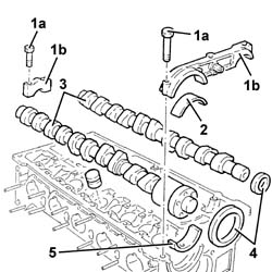
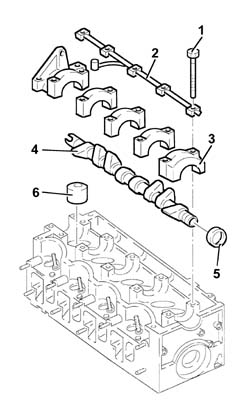
1. Undo the bolts (1a) and remove the camshaft caps (1b).
2. Remove the upper bearing shell for the front camshaft support, inlet side.
3. Remove the camshafts.
4. Remove the front camshaft oil seals.
5. Remove the lower bearing shell for the front camshaft support, inlet side.
Check that the end float of the camshaft is within the recommended values using a dial gauge.
| Measurement | Value | ||
|---|---|---|---|
| End float (mm) | 0.100 ÷ 0.230 |
If the end float of the camshaft is not within the recommended values, when reassembling the cylinder head, replace the worn components.
1. Undo the camshaft cap bolts.
2. Remove the camshaft support lubrication pipe.
3. Remove the camshaft caps.
4. Remove the camshaft.
5. Remove the camshaft front oil seal.
6. Remove the cups complete with valve clearance adjustment pads.
Remove the camshaft timing tools from the camshaft housing.
| Name | Country | |
|---|---|---|
| Gauge | 1.870.896.900 |
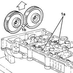
1. Release the camshafts (1a) as necessary and remove the camshaft sprockets (1b).
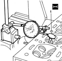
Check that the valve stem does not show signs of scoring or seizing.
Check that the diameter of the valve stems is within the recommended values; if this is not the case, replace the worn valves.
| Measurement | Value | ||
|---|---|---|---|
| Inlet and exhaust valve stem diameter (mm) | 5.974 - 5.992 |
Check that the thickness of the cylindrical part of the valve head is within the recommended values.
| Measurement | Value | ||
|---|---|---|---|
| Valve cylindrical section thickness (mm) | 1 |
Check that the diameter of the valve head is within the recommended values; if this is not the case, replace the valves.
| Measurement | Value | ||
|---|---|---|---|
| Exhaust and inlet valve outer diameter (mm) | 22.250 - 22.550 |
1. Check valve guide bore and valve clearance are within the recommended values or else the valve guide has to be replaced.
If necessary, replace the valve guides referring to op. 1016E14 single cylinder head valve guides - replace during operation 1016e10.
| Measurement | Value | ||
|---|---|---|---|
| Valve guide inner diameter (mm) | 6.022 - 6.040 |
| Measurement | Value | ||
|---|---|---|---|
| Valve stem - valve guide clearance (mm) | 0.030 - 0.066 |
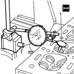
Check that the valve stem does not show signs of scoring or seizing.
Check that the diameter of the valve stems is within the recommended values; if this is not the case, replace the worn valves.
| Measurement | Value | ||
|---|---|---|---|
| Inlet and exhaust valve stem diameter (mm) | 5.90 ÷ 5.94 |
Check that the thickness of the cylindrical part of the valve head is within the recommended values.
| Measurement | Value | ||
|---|---|---|---|
| Valve cylindrical section thickness (mm) | 1 |
Check that the diameter of the valve head is within the recommended values; if this is not the case, replace the valves.
| Measurement | Value | ||
|---|---|---|---|
| Exhaust and inlet valve outer diameter (mm) | 22.55 ÷ 27.05 |
1. Check valve guide bore and valve clearance are within the recommended values or else the valve guide has to be replaced.
If necessary, replace the valve guides referring to op. - 1016E14 single cylinder head valve guides - replace during operation 1016e10.
| Measurement | Value | ||
|---|---|---|---|
| Valve guide inner diameter (mm) | 6.022 - 6.040 |
| Measurement | Value | ||
|---|---|---|---|
| Valve stem - valve guide clearance (mm) | 0.14 ÷ 0.082 |
Refit the valves, springs, caps and cotters using the same tools as used for the dismantling.
| Name | Country | |
|---|---|---|
| Lever | 1.860.790.000 |
| Name | Country | |
|---|---|---|
| Lever hook | 1.860.788.000 |
| Name | Country | |
|---|---|---|
| Extension | 1.860.787.000 |
| Name | Country | |
|---|---|---|
| Valve retaining base | 1.860.786.000 |
| Name | Country | |
|---|---|---|
| Chamber | 1.860.789.000 |
Remove the cylinder head from the vice.
Remove the support tool fitted initially from the cylinder head.
| Name | Country | |
|---|---|---|
| Support | 1.860.470.000 |
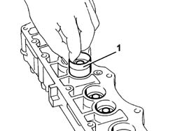
1. Remove the hydraulic tappets from the camshaft housing, taking care to place them on a suitable surface, making a note of their position in the camshaft housing.
Do not turn the tappets upsidedown or else they fluid they contain will escape.
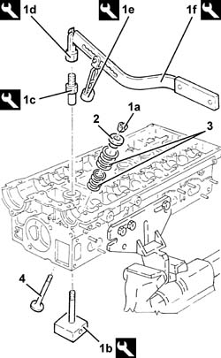
1. Remove the split collars (1a) using tools (1b), (1c), (1d), (1e) and (1f).
| Name | Country | |
|---|---|---|
| 1b | Valve retaining base | 1.860.786.000 |
| Name | Country | |
|---|---|---|
| 1c | Extension | 1.860.787.000 |
| Name | Country | |
|---|---|---|
| 1d | Lever hook | 1.860.788.000 |
| Name | Country | |
|---|---|---|
| 1e | Chamber | 1.860.840.000 |
| Name | Country | |
|---|---|---|
| 1f | Lever | 1.860.790.000 |
2. Remove the upper valve shim.
3. Remove the valve springs.
Remove the tools used for dismantling the valves.
4. Remove the valve.
Work in the same way to remove the remaining valves.
Remove the cylinder head from the vice.
Place a suitable wooden board between the support tools and the cylinder head to support the valves.
Refit the cylinder head in the vice.
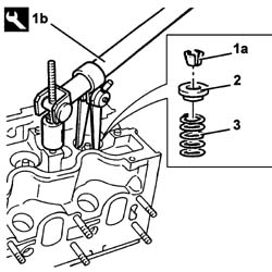
1. Remove cotters (1a) using tool (1b).
| Name | Country | |
|---|---|---|
| 1b | Tool | 1.860.644.000 |
2. Remove the upper valve shim.
3. Remove the valve spring.
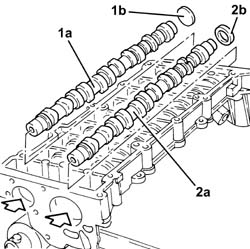
1. Using a suitable drift, extract the inlet side camshaft (1a) and the plug (1b).
2. Using a suitable drift, extract the exhaust side camshaft (2a) and the oil seal (2b).
Remove the exhaust side camshaft oil seal.
Grind the valve seats if the valves and valve guides are replaced.
| Measurement | Value | ||
|---|---|---|---|
| Upper band taper "a" () | 70° |
| Measurement | Value | ||
|---|---|---|---|
| Contact band with valve taper "b" () | 45° +/- 5' |
| Measurement | Value | ||
|---|---|---|---|
| Lower band taper "c" () | 15° |
| Measurement | Value | ||
|---|---|---|---|
| Contact band width with valve "I" (mm) | c.a. 2 |
Clean the valve seats thoroughly when the operation is complete.
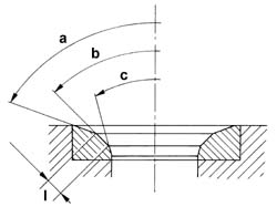
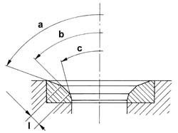
Grind the valve seats if the valves and valve guides are replaced.
| Measurement | Value | ||
|---|---|---|---|
| Upper section taper "" (-) | 45° ± 20' |
| Measurement | Value | ||
|---|---|---|---|
| Contact band with valve taper "b" (-) | 30° |
| Measurement | Value | ||
|---|---|---|---|
| Lower band taper"c" (-) | 15° |
| Measurement | Value | ||
|---|---|---|---|
| Contact band width with valve "I" (mm) | ~ 2 |
Clean the valve seats thoroughly when the operation is complete.
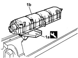
1. Fit the supporting tool (1a) on the camshaft housing (1b) and place it in the vice.
| Name | Country | |
|---|---|---|
| 1a | Support | 1.860.470.000 |
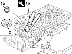
1. Remove the valve guide oil seal (1a) using the tool (1b).
| Name | Country | |
|---|---|---|
| 1b | Extractor | 1.860.989.000 |
2. Remove the lower valve shim.
1. Remove the valve guide oil seal (1a) using the tool (1b).
| Name | Country | |
|---|---|---|
| 1b | Extractor | 1.860.989.000 |
2. Remove the lower shim.
Work in the same way on the other valves.
Remove the cylinder head from the support tools and recover the valves.
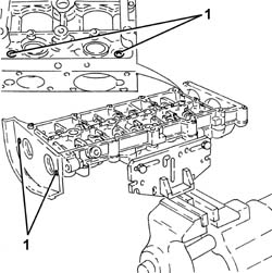
1. Undo and remove the engine oil lubrication duct plugs.
Use the appropriate tool to check that the characteristics of the springs are within the recommended values; if this is not the case, replace parts that have yielded.
| Measurement | Value | ||
|---|---|---|---|
| Spring height (mm) | 31 | ||
| Under load (daN) | 22.5 | ||
| Measurement | Value | ||
|---|---|---|---|
| Spring height (mm) | 23 | ||
| Under load (daN) | 42.3 | ||
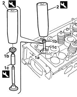
1. Fit the lower valve shims (1a); position the oil seals (1b) on the valve guides, using the drift (1c) on the stem pf the valve temporarily fitted in the seat, then fit the new oil seal on the drift.
2. Fit the oil seal in its seat using drift (2a).
| Name | Country | |
|---|---|---|
| 1c | Drift | 1.860.993.000 |
| Name | Country | |
|---|---|---|
| 2a | Drift | 1.860.993.000 |
Use the appropriate tool to check that the characteristics of the springs are within the recommended values; if this is not the case, replace parts that have yielded.
| Measurement | Value | ||
|---|---|---|---|
| Spring height (mm) | 33.6 | ||
| Under load (daNm) | 16.7 | ||
| Measurement | Value | ||
|---|---|---|---|
| Spring height (mm) | 25.2 | ||
| Under load (daN) | 36.6 | ||
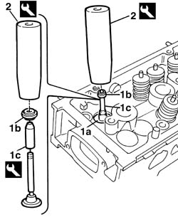
1. Fit the lower valve shims (1a); position the oil seals (1b) on the valve guides, using the drift (1c) on the stem pf the valve temporarily fitted in the seat, then fit the new oil seal on the drift.
2. Fit the oil seal in the housing using the drift illustrated.
| Name | Country | |
|---|---|---|
| 1c | Drift | 1.860.993.000 |
| Name | Country | |
|---|---|---|
| 2 | Drift | 1.860.993.000 |
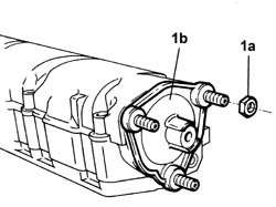
1. Undo the nut (1a) and remove the rear cover (1b).
Remove the camshaft, complete with oil seal, from the housing.
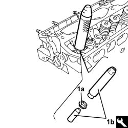
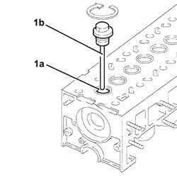
1. Remove the valve guides (1a) using the tool (1b).
| Name | Country | |
|---|---|---|
| 1b | Drift | 1.860.395.000 |
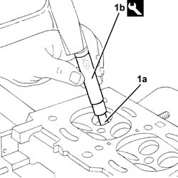
Position the cylinder head on the workbench.
1. Screw the special extraction tool (1b) in the valve seat (1a).
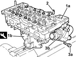
Remove the support tool, complete with upper cylinder head from the vice and separate them.
LOWER CYLINDER HEAD.
1. Position the lower cylinder head (1a) in the vice using the tool (1b).
| Name | Country | |
|---|---|---|
| 1b | Mount | 1.860.470.001 |
2. Remove the hydraulic tappets.
3. Undo the bolts (3a) and remove the thermostat (3b).
Remove the gasket.
Refit the valves, springs, caps and cotters using the same tools as used for the dismantling.
| Name | Country | |
|---|---|---|
| Lever | 1.860.790.000 |
| Name | Country | |
|---|---|---|
| Lever hook | 1.860.788.000 |
| Name | Country | |
|---|---|---|
| Extension | 1.860.787.000 |
| Name | Country | |
|---|---|---|
| Valve retaining base | 1.860.786.000 |
| Name | Country | |
|---|---|---|
| Chamber | 1.860.877.000 |
Fit the timing belt tensioner.
Fit the thermostat and gasket.
Remove the cylinder head from the vice.
Remove the cylinder head support tool.
| Name | Country | |
|---|---|---|
| Support | 1.860.470.000 |
Measure the diameters of the camshaft housing supports, checking that the figures correspond to the recommended values; if this is not the case, replace the damaged camshaft housing.
| Measurement | Value | ||
|---|---|---|---|
| Diameter of 1st° camshaft bearing, inlet side, in camshaft housing (mm) | 29.989 - 30.014 |
| Measurement | Value | ||
|---|---|---|---|
| Diameter of 2nd° camshaft support, inlet side in camshaft housing (mm) | 52.445 - 52.470 |
| Measurement | Value | ||
|---|---|---|---|
| Diameter of 3rd° camshaft bearing, inlet side, in camshaft housing (mm) | 52.845 - 52.870 |
| Measurement | Value | ||
|---|---|---|---|
| Diameter of 4th° camshaft bearing, inlet side, in camshaft housing (mm) | 53.245 - 53.270 |
| Measurement | Value | ||
|---|---|---|---|
| Diameter of 5th° camshaft bearing, inlet side, in camshaft housing (mm) | 53.645 - 53.670 |
Measure the camshaft bearings, checking that the values correspond to the recommended figures; if this is not the case, replace the damaged camshaft.
| Measurement | Value | ||
|---|---|---|---|
| Diameter of 1st° camshaft bearing, timing side (mm) | 29.944 - 29.960 |
| Measurement | Value | ||
|---|---|---|---|
| Diameter of 2nd° camshaft bearing, timing side (mm) | 52.400 - 52.415 |
| Measurement | Value | ||
|---|---|---|---|
| Diameter of 3rd° camshaft bearing, timing side (mm) | 52.800 - 52.815 |
| Measurement | Value | ||
|---|---|---|---|
| Diameter of 4th° camshaft bearing, timing side (mm) | 53.200 - 53.215 |
| Measurement | Value | ||
|---|---|---|---|
| Diameter of 5th° camshaft bearing, timing side (mm) | 53.600 - 53.615 |
Check that the nominal lift of the camshaft cams is within the recommended values; if this is not the case, replace the worn camshat.
| Measurement | Value | ||
|---|---|---|---|
| Camshaft cam height (mm) | Exhaust | 8 | |
| Inlet | 8.5 | ||
Also check that the surfaces of the cams and the bearings do not show signs of wear, grooves or seizing.
Fit the camshafts in the camshaft housings, taking into account that the recommended clearance should not be exceeded.
| Measurement | Value | ||
|---|---|---|---|
| Clearance between camshaft bearings- camshaft housing. supports (mm) | 0.030 - 0.070 |
1. Fit the new oil seal (1a) on the camshaft housings, using the tool (1b).
| Name | Country | |
|---|---|---|
| 1b | Fitting tool | 1.860.882.000 |
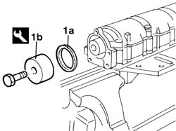
Reassembling
Clean the residues of the old gasket from the lower surface of the cylinder head.
Check that the planarity of the lower cylinder head surface is within the recommended values.
| Measurement | Value | ||
|---|---|---|---|
| Flatness of bottom surface (mm) | 0.1 |
If the planarity of the lower cylinder head surface is not within the recommended values, regrind the lower cylinder head surface without exceeding the minimum permissible height.
| Measurement | Value | ||
|---|---|---|---|
| Minimum permissible height after refacing (mm) | 140,85 |
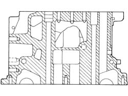
Turn the cylinder head upside down on the workbench.
1. Remove the valve seat (1a) using the extraction tool (1b).
Work in the same way on the other valves.
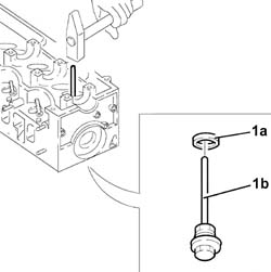
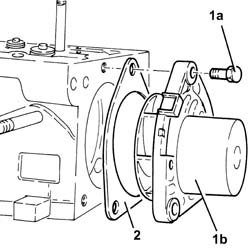
1. Undo the bolts (1a) and remove the water pump (1b).
2. Remove the gasket.
Measure the diameters of the tappet housings, checking that the values correspond to the recommended figures; if this is not the case, replace the camshaft housing.
| Measurement | Value | ||
|---|---|---|---|
| Diameter of tappet housings (mm) | 33.000 - 33.025 |
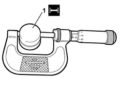
1. Measure the diameters of the tappets, checking that the values are within the recommended figures; if this is not the case, replace the tappets.
| Measurement | Value | ||
|---|---|---|---|
| 1 | Tappet external diameter (mm) | 32.959 - 32.975 |
When the cylinder head has been refaced, check that the volume of the combustion chamber (with the valve and spark plugs temporarily fitted) is within the recommended values.
| Measurement | Value | ||
|---|---|---|---|
| Combustion chamber volume (c.c.) | 51,486 |
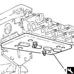
To replace the valve guides - 1016E14 single cylinder head valve guides - replace during operation 1016e10.
1. Place a wooden board on the cylinder head surface to support the valves and bolt in place.
| Name | Country | |
|---|---|---|
| 1 | Stand | 1.860.804.001 |
Fit the hydraulic tappets in the special housings in the camshaft housing.
Calculate the tappet clearance with seat in the camshaft housing, checking that the values correspond to the recommended figures.
| Measurement | Value | ||
|---|---|---|---|
| Clearance between housing in head - hydraulic tappet (mm) | 0.025 - 0.066 |
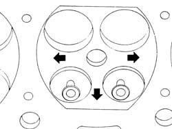
If the volume of the combustion chamber is not within the recommended figures, restore it by removing material from the inside of the combustion chamber at the points shown by the arrows.
Reassembling
Clean the residues of the old gasket from the lower surface of the cylinder head.
Check that the planarity of the lower cylinder head surface is within the recommended values.
| Measurement | Value | ||
|---|---|---|---|
| Flatness of bottom surface (mm) | 0.1 |
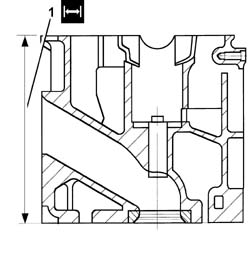
1. If the planarity of the lower cylinder head surface is not within the recommended values, regrind the lower cylinder head surface without exceeding the minimum permissible height.
| Measurement | Value | ||
|---|---|---|---|
| 1 | Permissible minimum height (mm) | 140.85 ÷ 141.15 |
1. Remove the cotters (1a) using tools (1b) and (1c).
| Name | Country | |
|---|---|---|
| 1b | Lever | 1.860.644.001 |
| Name | Country | |
|---|---|---|
| 1c | Chamber | 1.870.890.000 |
2. Remove the upper valve shim.
3. Remove the valve spring.
4. Remove the shim (for the exhaust valves only).
5. Remove the valve guide oil seal with built-in lower valve shim.
Work in the same way on the other valves.
De-carbonize the valves and check that the stem does not show signs of grooves.
Check that the diameter of the valve stems is within the recommended values; if this is not the case, replace the worn valves.
| Measurement | Value | ||
|---|---|---|---|
| Inlet valve stem diameter (mm) | 6.975 - 6.990 |
| Measurement | Value | ||
|---|---|---|---|
| Exhaust valve stem diameter (mm) | 6.960 - 6.975 |
Check that the diameter of the valve guide is within the recommended values; if this is not the case, replace the valve guides.
The diameter of the valve guide is checked with the guide fitted in the head.
| Measurement | Value | ||
|---|---|---|---|
| Valve guide diameter (mm) | Exhaust | 7,022 - 7,040 | |
| Inlet | 7,022 - 7,040 | ||
Check that the outer diameter of the hydraulic tappets is within the recommended values. if this is not the case, replace the worn parts.
| Measurement | Value | ||
|---|---|---|---|
| Outer diameter (mm) | 32.959 - 32.975 |
Check that the diameter of the hydraulic tappets in the cylinder head is within the recommended values; If this is not the case, replace the cylinder head.
| Measurement | Value | ||
|---|---|---|---|
| Diameter of hydraulic tappet seats (mm) | 33.000 - 33.025 |
Use a torque wrench to check that the valve spring specifications are within specified values; if this is not the case, replace parts that have yielded.
| Measurement | Value | ||
|---|---|---|---|
| Internal free spring length (mm) | 31,20 |
| Measurement | Value | ||
|---|---|---|---|
| Inner spring length (mm) | 29.5 | ||
| Check load (daN) | 8.650 - 7.550 | ||
| Measurement | Value | ||
|---|---|---|---|
| Inner spring length (mm) | 23.4 | ||
| Check load (daN) | 18.060 - 16.260 | ||
| Measurement | Value | ||
|---|---|---|---|
| Outer spring free length (mm) | 46,00 |
| Measurement | Value | ||
|---|---|---|---|
| Outer spring length (mm) | 36.80 | ||
| Check load (daN) | 22.780 - 20.580 | ||
| Measurement | Value | ||
|---|---|---|---|
| Outer spring length (mm) | 27.6 | ||
| Check load (daN) | 44.965 - 41.365 | ||
Check that the surfaces of the camshaft bearings and cams do not show signs of wear, grooves or seizing; if this is not the case, replace the camshafts.
Check that the cam journal diameters are within the recommended values; if this is not the case, replace the worn camshat.
| Measurement | Value | ||
|---|---|---|---|
| Intake pin diameter v.d.f (mm) | 49,985 - 50,000 |
| Measurement | Value | ||
|---|---|---|---|
| Journal diameter (mm) | 26.000 - 26.015 |
| Measurement | Value | ||
|---|---|---|---|
| Camshaft half-bearing thickness asp. v.d.f (mm) | 2,998 - 2,982 |
| Measurement | Value | ||
|---|---|---|---|
| Working clearance (mm) | 0,034 - 0,086 |
Check that the nominal lift of the camshaft cams is within the recommended values; if this is not the case, replace the worn camshat.
| Measurement | Value | ||
|---|---|---|---|
| Inlet shaft nominal cam lift (mm) | 9.0 |
| Measurement | Value | ||
|---|---|---|---|
| Exhaust shaft nominal cam lift (mm) | 9.0 |
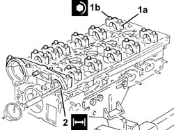
1. Fit the camshaft caps (1a) on the cylinder head and tighten the bolts (1b) to torque.
| Fastening | Component | Ø | Value (daNm) | |
|---|---|---|---|---|
| 1b | Bolt | CAMSHAFT CAPS | M7 | (Cylinder head side) 1.4 ÷ 2.0 |
2. Check the diameter of the camshaft mounts is within specified values; If this is not the case, replace the cylinder head.
| Measurement | Value | ||
|---|---|---|---|
| .intake. camshaft mount diameter v.d.f (mm) | 56,015 - 55,990 |
| Measurement | Value | ||
|---|---|---|---|
| 2 | Camshaft bearing diameter (mm) | 26.045 ÷ 26.070 |
Check that the valves do not show signs of scoring or seizing.
Check that the diameter of the valve stems is within the recommended values; if this is not the case, replace the worn valves.
| Measurement | Value | ||
|---|---|---|---|
| Stem diameter (mm) | 7.890 ÷ 7.940 |
With the valve guide fitted in the head, check that the diameter is within the recommended values, if this is not the case, replace the valve guides.
| Measurement | Value | ||
|---|---|---|---|
| Diameter (mm) | 8.040 ÷ 8.022 |
Check that the outer diameter of the cups is within the recommended values. if this is not the case, replace the worn parts.
| Measurement | Value | ||
|---|---|---|---|
| Outer diameter (mm) | 36.975 ÷ 36.991 |
Check that the diameter of the cup housings are within the recommended values; If this is not the case, replace the cylinder head.
| Measurement | Value | ||
|---|---|---|---|
| Cup seat diameter (mm) | 37.000 - 37.025 |
Check that the length of the uncompressed valve springs is within the recommended values.
| Measurement | Value | ||
|---|---|---|---|
| Released spring length (mm) | 53.9 |
Use a torque wrench to check that the spring specifications are within specified values; if this is not the case, replace parts that have yielded.
| Measurement | Value | ||
|---|---|---|---|
| Length (mm) | 43.12 | ||
| Under load (daN) | 24.5 - 21.5 | ||
| Measurement | Value | ||
|---|---|---|---|
| Length (mm) | 26.5 | ||
| Under load (daN) | 56 - 61 | ||
Check that the cam journal diameters are within the recommended values; if this is not the case, replace the worn camshat.
| Measurement | Value | ||
|---|---|---|---|
| Journal diameter (mm) | 26.000 - 26.015 |
Check that the nominal lift of the camshaft cams is within the recommended values; if this is not the case, replace the worn camshat.
| Measurement | Value | ||
|---|---|---|---|
| Nominal cam lift (mm) | Exhaust | 9.0 | |
| Intake | 8.5 | ||
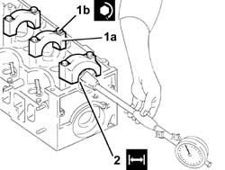
1. Fit the camshaft caps (1a) on the cylinder head and tighten the bolts (1b) to torque.
| Fastening | Component | Ø | Value (daNm) | |
|---|---|---|---|---|
| 1b | Bolt | CAMSHAFT CAPS | M7 | (Cylinder head side) 1.4 ÷ 2.0 |
2. Check the diamter of the camshaft mounts is within specified values; If this is not the case, replace the cylinder head.
| Measurement | Value | ||
|---|---|---|---|
| 2 | Diameter (mm) | 26.045 - 26.070 |
Remove the wooden board and recover the valves.
| Name | Country | |
|---|---|---|
| Stand | 1.860.804.001 |
Remove the lower cylinder head from the support tool.
| Name | Country | |
|---|---|---|
| Mount | 1.860.470.001 |
Replace the valve guides - 1016E14 single cylinder head valve guides - replace during operation 1016e10.
Check that the outer diameter of the valve guides to be fitted is within the recommended values.
| Measurement | Value | ||
|---|---|---|---|
| Outer diameter (mm) | 13.010 - 13.030 |
1. Fit the valve guide oil seals (1a) using the tool (1b).
| Name | Country | |
|---|---|---|
| 1b | Fitting tool | 1.860.812.000 |
Before fitting the new valve guides, heat the cylinder head in the oven to a temperature of 80 - 100 °C.
Check that the outer diameter of the valve seats to be fitted is within the recommended values.
| Measurement | Value | ||
|---|---|---|---|
| Outer diameter (mm) | Exhaust | 35.142 - 35.157 | |
| Inlet | 36.135 - 36.150 | ||
1. Fit the valve seats (1a) using a suitable tool (1b).
Reassembling
Clean the residues of the old gasket from the lower surface of the lower cylinder head.
Check that the planarity of the lower cylinder head surface is within the recommended values.
| Measurement | Value | ||
|---|---|---|---|
| Flatness of bottom surface (mm) | 0.1 ± 0.05 |
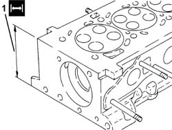
1. If the planarity of the lower cylinder head surface is not within the recommended values, regrind it without exceeding the minimum permissible height.
| Measurement | Value | ||
|---|---|---|---|
| Permissible minimum height (mm) | 107.0 ± 0.05 |
In the case of slight distortions suffered during fitting, ream the inner diameter of the valve guides to the recommended value.
| Measurement | Value | ||
|---|---|---|---|
| Inner diameter (bore) (mm) | 7.022 - 7.040 |
Regrind the valve seats each time the valves or the valve guides are replaced.
1. Regrinding a valve seat with the cutter at 44° 30'.
Reduce the valve seat from above with the cutter at 20° and from below with the cutter at 75°, until the width of the band in contact with the valves is correct.
| Measurement | Value | ||
|---|---|---|---|
| Valve contact band width (mm) | ~ 2 |
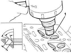
1. Regrind the valve seats to the recommended dimension.
| Measurement | Value | ||
|---|---|---|---|
| 1 | Contact band angle with valve (-) | 45°30' ± 1? |
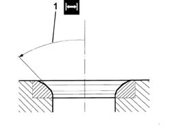
Check that the valves do not show signs of scoring or seizing.
Check that the diameter of the valve stems is within the recommended values; if this is not the case, replace the worn valves.
| Measurement | Value | ||
|---|---|---|---|
| Stem diameter (mm) | Exhaust | 5.972 ÷ 5.990 | |
| Inlet | 5.982 ÷ 6.000 | ||
Check that the length of the uncompressed valve springs is within the recommended values.
| Measurement | Value | ||
|---|---|---|---|
| Free length (mm) | 43.1 |
Use a torque wrench to check that the valve spring specifications are within specified values; if this is not the case, replace parts that have yielded.
| Measurement | Value | ||
|---|---|---|---|
| Length (mm) | 34.0 | ||
| Under load (daN) | 20.17 ÷ 21.42 | ||
| Measurement | Value | ||
|---|---|---|---|
| Length (mm) | 24.5 | ||
| Under load (daN) | 42.82 ÷ 45.47 | ||
Check that the cam journal diameters are within the recommended values; if this is not the case, replace the worn camshaft(s).
| Measurement | Value | ||
|---|---|---|---|
| Journal diameter (mm) | Fifth pin | 30.000 ÷ 30.015 | |
| First pin | 43.600 ÷ 43.615 | ||
| Fourth pin | 43.000 ÷ 43.015 | ||
| Second pin | 43.400 ÷ 43.415 | ||
| Third pin | 43.200 ÷ 43.215 | ||
Check that the nominal lift of the camshaft cams is within the recommended values; if this is not the case, replace the worn camshaft(s).
| Measurement | Value | ||
|---|---|---|---|
| Nominal cam lift (mm) | Exhaust | 8.0 | |
| Inlet | 8.0 | ||
1. Check the diameter of the camshaft mounts is within specified values; If this is not the case, replace the cylinder head.
| Measurement | Value | ||
|---|---|---|---|
| Support diameter (mm) | Fifth support | 30.045 ÷ 30.070 | |
| First support | 43.646 ÷ 43.671 | ||
| Fourth support | 43.046 ÷ 43.071 | ||
| Second support | 43.446 ÷ 43.471 | ||
| Third support | 43.246 ÷ 43.271 | ||
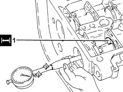
Measure the contact line of each valve against its seat; if the contact is not centred, make the appropriate reductions as described above.
1. Temporarily fit the valves and the spark plugs and carry out the valve compression leakage test using tools (1a) and (1b).
| Name | Country | |
|---|---|---|
| 1a | Lever | 1.860.490.000 |
| Name | Country | |
|---|---|---|
| 1b | Test instrument | 1.895.868.000 |
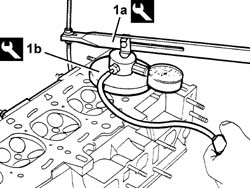
Grind the valve seats using a suitable tool.
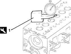
Temporarily fit the valves.
1. Check that the valve recess in relation to the cylinder head is within the recommended values, using a tool fitted with a dial gauge.
| Measurement | Value | ||
|---|---|---|---|
| 1 | Recess from cylinder head surface (mm) | 0.1 - 0.5 |
| Name | Country | |
|---|---|---|
| 1 | Dial gauge mounting | 1.870.404.000 |
If the valve recess in relation to the cylinder head plane is not within the recommended value, regrind the valve seats.
The outer diameter of the valve seats should be as follows.
| Measurement | Value | ||
|---|---|---|---|
| Outer diameter (mm) | Exhaust | 27.491 ÷ 27.512 | |
| Inlet | 29.489 ÷ 29.514 | ||
1. Regrind the valve seats to the recommended dimension.
| Measurement | Value | ||
|---|---|---|---|
| Contact band angle with inlet valve () | 45° ± 20' |
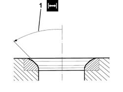
Fit the lower valve shims back in their housings.
1. Fit the valve guide oil seals (1a) using the tools (1b) and (1c).
| Name | Country | |
|---|---|---|
| 1b | Drift | 1.860.813.000 |
| Name | Country | |
|---|---|---|
| 1c | Fitting tool | 1.860.454.000 |
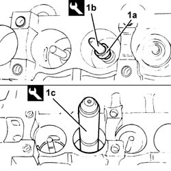
Place a suitable wooden board between the support tools and the cylinder head to support the valves.
Fit the cylinder head, complete with valves, on the support tools and fix it using the nuts.
Fit the lower shim.
1. Fit the valve guide oil seals (1a) using the tools (1b) and (1c).
| Name | Country | |
|---|---|---|
| 1b | Drift | 1.860.814.001 |
| Name | Country | |
|---|---|---|
| 1c | Fitting tool | 1.860.313.000 |
| Name | Country | |
|---|---|---|
| 1d | Drift | 1.867.019.000 |
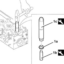
Grind the valve seats using a suitable tool.
LOWER CYLINDER HEAD.
Position the lower cylinder head in the vice using the tool.
| Name | Country | |
|---|---|---|
| Mount | 1.860.470.001 |
Fit the valves in their seats, then support them using the wooden board and secure them using bolts.
| Name | Country | |
|---|---|---|
| Stand | 1.860.804.001 |
1. Refit the valve guide oil seal (1a) in its housing using the tool (1b).
| Name | Country | |
|---|---|---|
| 1b | Fitting tool | 1.870.897.100 |
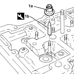
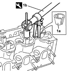
1. Fit the valve (1a) and support it using the tools (1b) and (1c).
| Name | Country | |
|---|---|---|
| 1b | Valve retaining base | 1.860.786.000 |
| Name | Country | |
|---|---|---|
| 1c | Extension | 1.860.787.000 |
2. Place the valve springs back in their housings.
3. Place the upper valve shim back in its housing.
4. Place the split cotters (4a) back in their housings using the tools (4b), (4c) and (4d).
| Name | Country | |
|---|---|---|
| 4b | Lever hook | 1.860.788.000 |
| Name | Country | |
|---|---|---|
| 4c | Chamber | 1.860.840.000 |
| Name | Country | |
|---|---|---|
| 4d | Lever | 1.860.790.000 |
Work in the same way when fitting the remaining valves.
Remove the tools used for refitting the valves.
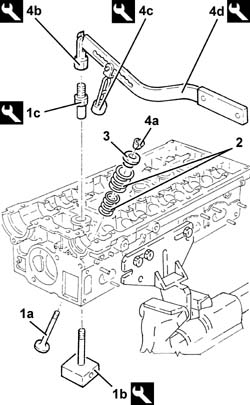
Fit the valve spring.
Fit the upper valve shim.
| Name | Country | |
|---|---|---|
| se | Tool | 1.860.644.000 |
Work in the same way on the other valves.
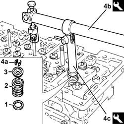
1. Place the shim back in its housing (exhaust valves only).
2. Place the valve spring back in its housing.
3. Place the upper valve shim back in its housing.
4. Place the split cotters (4a) back in their housings using the tools (4b) and (4c).
| Name | Country | |
|---|---|---|
| 4b | Lever | 1.860.644.001 |
| Name | Country | |
|---|---|---|
| 4c | Chamber | 1.870.890.000 |
Work in the same way on the other valves.
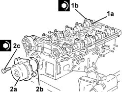
Place the inlet side camshaft front support lower bearing shell back in its housing.
Place the camshafts back in their housings.
Place the inlet side camshaft front support upper bearing shell back in its housing.
1. Place the camshft caps (1a) back in their housings and secure them tightening the bolts (1b) to the recommended torque.
| Fastening | Component | Ø | Value (daNm) | |
|---|---|---|---|---|
| 1b | Bolt | CAMSHAFT CAPS | M7 | (Cylinder head side) 1.4 ÷ 2.0 |
2. Place the water pump (2a), complete with O-Ring (2b), back in its housing and secure it tightening the bolts (2c) to the recommended torque.
| Fastening | Component | Ø | Value (daNm) | |
|---|---|---|---|---|
| 2c | Bolt | COOLANT PUMP | M8 | (Cylinder head side) 2.3 ÷ 3.3 |
Remove the cylinder head from the supporting tools.
Remove the wooden board supporting the valves from the support tools.
Refit the cylinder head on the support tools.
Fit the cups complete with valve clearance adjustment pads.
Fit the camshaft.
1. Fit the camshaft caps.
Fit the camshaft journal lubrication pipe.
2. Tighten the camshaft cap bolts to the specified torque.
| Fastening | Component | Ø | Value (daNm) | |
|---|---|---|---|---|
| 2 | Bolt | CAMSHAFT CAPS | M7 | (Cylinder head side) 1.4 ÷ 2.0 |
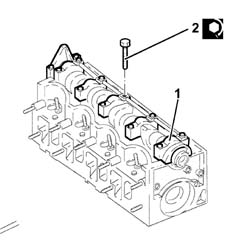
Remove the wooden board for supporting the valves from the cylinder head plane.
| Name | Country | |
|---|---|---|
| Stand | 1.860.804.001 |
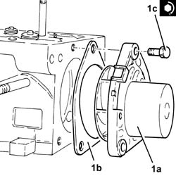
1. Place the water pump (1a), complete with gasket (1b), back in its housing and tighten the bolts (1c) to the recommended torque.
| Fastening | Component | Ø | Value (daNm) | |
|---|---|---|---|---|
| 1c |
Place the cam angle sensor back in its housing and fix it using the bolt.
| Fastening | Component | Ø | Value (daNm) | |
|---|---|---|---|---|
| Bolt | CAM ANGLE SENSOR | 0,9 - 1,2 |
1. Fit the front camshaft oil seal, exhaust side (1a) using the tool (1b).
| Name | Country | |
|---|---|---|
| 1b | Fitting tool | 1.860.824.000 |
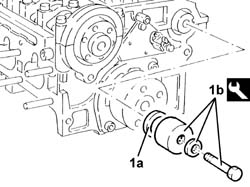
1. Fit camshaft front oil seal (1a) using tool (1b).
| Name | Country | |
|---|---|---|
| 1b | Fitting tool | 1.821.824.000 |
2. Fit the heater plugs and tighten them to the recommended torque.
| Fastening | Component | Ø | Value (daNm) | |
|---|---|---|---|---|
| 2 | GLOW PLUGS | M12 | (Cylinder head side) 1.4 - 1.8 |
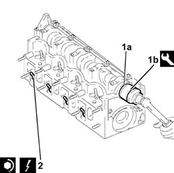
1. Place the thermostat (1a), complete with gasket, back in its housing and secure it tightening the bolts (1b) to the recommended torque.
| Fastening | Component | Ø | Value (daNm) | |
|---|---|---|---|---|
| 1b |
2. Place the hydraulic tappets in their housings.
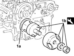
1. Fit the front camshaft oil seal, inlet side (1a) using the tool (1b).
| Name | Country | |
|---|---|---|
| 1b | Fitting tool | 1.860.844.000 |
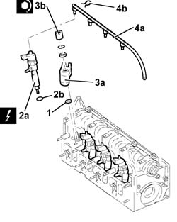
1. Fit the injector bracket support pads.
2. Fit injectors (2a) complete with seals (2b).
3. Fit injector brackets (3a) and tighten nuts (3b) to torque.
| Fastening | Component | Ø | Value (daNm) | |
|---|---|---|---|---|
| 3b | Nut | INJECTORS(DIESEL) | M8 | (Cylinder head side) 2.7 - 4.0 |
4. Position the connectors for the pipe from the injectors to the fuel recovery manifold (4a) on the corresponding injector seats and fully insert them until the click of the spring (4b) is heard.
Remove the lower cylinder head from the support tool.
| Name | Country | |
|---|---|---|
| Mount | 1.860.470.001 |
CAMSHAFT HOUSING
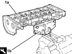
1. Position the upper cylinder head (1a) in the vice using the tool (1b).
| Name | Country | |
|---|---|---|
| 1b | Mount | 1.860.470.001 |
Place the timing belt side guards back in their housings and secure them using the bolts.
| Fastening | Component | Ø | Value (daNm) | |
|---|---|---|---|---|
| Bolt | PROTECTION COVER GUARDS/SUPPORTS | 0,9 - 1,2 |
1. Place the inlet side timing driven pulley back in its housing.
2. Tighten th bolts (2a) for the inlet side timing driven pulley to the recommended torque using the tool (2b) for counter-torque.
| Fastening | Component | Ø | Value (daNm) | |
|---|---|---|---|---|
| 2a | Bolt | TIMING GEAR DRIVEN PULLEYS | M6 | (Intake camshaft side) 0.9 - 1.2 |
| Name | Country | |
|---|---|---|
| 2b | Counter-torque | 1.860.856.000 |
3. Place the exhust side timing driven pulley back in its housing.
4. Tighten the bolt (4a) for the exhaust side timing driven pulley to the recommended torque using the tools (4b) and (4c) for counter-torque.
| Fastening | Component | Ø | Value (daNm) | |
|---|---|---|---|---|
| 4a | Bolt | TIMING GEAR DRIVEN PULLEYS | M12 | (Exhaust camshaft side) 11.00 - 15.9 |
| Name | Country | |
|---|---|---|
| 4b | Support for counter-torque | 1.860.831.000 |
| Name | Country | |
|---|---|---|
| 4c | Counter-torque | 1.860.848.000 |
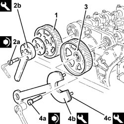
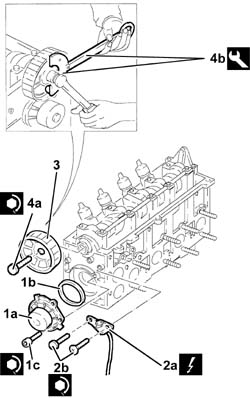
1. Fit the water pump (1a), complete with a new O-ring (1b), and tighten the bolts (1c) to torque.
| Fastening | Component | Ø | Value (daNm) | |
|---|---|---|---|---|
| 1c | Bolt | COOLANT PUMP | M8 | (Engine block side) 2.3 - 3.3 |
2. Fit the cam angle sensor (2a) and tighten the bolts (2b).
| Fastening | Component | Ø | Value (daNm) | |
|---|---|---|---|---|
| 2b | Bolt | ENGINE RPM SENSOR | 0.9 - 1.2 |
3. Fit the driven pulley.
4. Tighten the bolt for the driven pulley (4a) to the recommended torque usign the tools (4b).
| Fastening | Component | Ø | Value (daNm) | |
|---|---|---|---|---|
| 4a | Bolt | TIMING DUCT PULLEY | M12 | 11.0 - 15.9 |
| Name | Country | |
|---|---|---|
| 4b | Support for counter-torque | 1.860.831.000 |
| Name | Country | |
|---|---|---|
| 4b | Counter-torque | 1.860.831.001 |
Tighten the engine oil lubrication duct plugs.
Place the camshafts back in their housings.
Place the camshaft gears back in their housings and secure them without tightening the bolts.
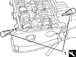
1. Fit the camshaft timing tools.
Check that the tools are correctly inserted in the housings in the camshafts.
| Name | Country | |
|---|---|---|
| 1 | Gauge | 1.870.896.900 |
Place the thermostat, complete with gasket, back in its housing and fix it tightening the bolts to the recommended torque.
| Fastening | Component | Ø | Value (daNm) | |
|---|---|---|---|---|
| Bolt | THERMOSTAT | M8 | (Cylinder head side) 2.3 ÷ 3.3 |
Refit the inlet manifold gasket.
Place the inlet manifold, complete with modular inlet manifold and butterfly casing, back in its housing, then secure it tightening the nuts to the recommended torque.
| Fastening | Component | Ø | Value (daNm) | |
|---|---|---|---|---|
| Nut | INLET MANIFOLD | M8 | (Cylinder head side) 2.3 ÷ 3.3 |
Connect the electrical connection for the cam angle sensor.
Connect the earth lead to the cylinder head.
Connect the coolant return pipe to the engine coolant reservoir, thermostat side.
Connect the electrical connection to the engine coolant temperature sensor.
Place the spark plugs back in their housings and tighten them to the recommended torque.
| Fastening | Component | Ø | Value (daNm) | |
|---|---|---|---|---|
| SPARK PLUGS | M14 | (Cylinder head side) 2.5 ÷ 3.0 |
Remove the cylinder head from the vice and place the support tool back in its housing.
| Name | Country | |
|---|---|---|
| Support | 1.860.470.000 |
Check that the valve clearance, with the valves in the closed position, is within the recommended values. if not replace the valve clearance adjustment shims as described below.
| Measurement | Value | ||
|---|---|---|---|
| Clearance with valve in closed position (mm) | Exhaust | 0.30 - 0.40 | |
| Inlet | 0.30 - 0.40 | ||
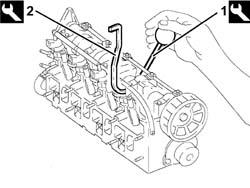
1. Lower the tappet in question using the tool.
| Name | Country | |
|---|---|---|
| 1 | Lever | 1.860.443.000 |
2. Fit the tool.
| Name | Country | |
|---|---|---|
| 2 | Lever | 1.860.724.001 |
Remove the tool.
| Name | Country | |
|---|---|---|
| Lever | 1.860.443.000 |
Extract the valve clearance adjustment pad and replace it with another of a suitable size (smaller for a smaller clearance and larger for a larger clearance).
Remove the tool.
| Name | Country | |
|---|---|---|
| Lever | 1.860.724.001 |
1. Tighten the camshaft sprocket fixing bolts to the recommended torque.
| Fastening | Component | Ø | Value (daNm) | |
|---|---|---|---|---|
| 1 |
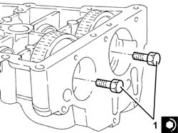
1. Fit the gasket.
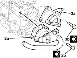
2. Fit the thermostat (2a), complete with pipes and sensors, and tighten the bolts (2b) to torque.
| Fastening | Component | Ø | Value (daNm) | |
|---|---|---|---|---|
| 2b | Bolt | THERMOSTAT | M8 | 1.4 ÷ 2.0 |
3. Fit the vacuum unit (3a), complete with O-ring, and tighten the bolts (3b) to torque.
| Fastening | Component | Ø | Value (daNm) | |
|---|---|---|---|---|
| 3b | Bolt | BRAKE SERVO VACUUM PUMP | M8 | 2.3 - 3.3 |
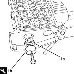
1. Fit the front camshaft oil seal, exhaust side (1a) using the tool (1b).
| Name | Country | |
|---|---|---|
| 1b | Fitting tool | 1.870.896.800 |
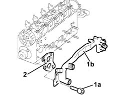
1. Fit the gasket.
2. Fit the water pump rigid inlet pipe (2a) and tighten the bolts (2b).
Connect the supply pipe from the thermostat to the water return manifold to the pump, manifold side.
| Fastening | Component | Ø | Value (daNm) | |
|---|---|---|---|---|
| 2b | Bolt | COOLANT PUMP RIGID INLET PIPE | M6 | 0.9 - 1.2 |
Fit the inlet side camshaft plug.
Fit the exhaust side timing drive pulley and fix it with the bolt without tightening it.
1. Place the cam angle sensor (1a) back in its housing and secure it tightening the bolt (1b) to the recommended torque.
| Fastening | Component | Ø | Value (daNm) | |
|---|---|---|---|---|
| 1b |
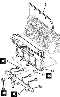
1. Fit air intake manifold assembly (1a) and tighten nuts (1b).
| Fastening | Component | Ø | Value (daNm) | |
|---|---|---|---|---|
| 1b | Nut | INLET MANIFOLD | 2.3 - 3.3 |
Connect the coolant return pipe to the expansion tank and the system vent pipe to the engine thermostat.
Position the heater plugs supply cable and fix it using the nuts.
2. Connect the fuel return pipe for lubricating the injectors to the fuel manifold.
Fit new pipes from fuel manifold to fuel injectors on the fuel manifold without tightening the relevant connectors.
3. Fit the fuel distribution manifold (3a), complete with pipes and fuel pressure sensor, and tighten the nuts (3b).
| Fastening | Component | Ø | Value (daNm) | |
|---|---|---|---|---|
| 4 | Nut | INJECTOR FUEL MANIFOLD (DIESEL) | 2.3 - 3.3 |
4. Tighten the injector side connectors to the recommended torque.
| Fastening | Component | Ø | Value (daNm) | |
|---|---|---|---|---|
| 4 | Connector | FUEL MANIFOLD LINE TO INJECTORS | M12 | (Injectorside ) 2.3 - 3.3 |
5. Tighten the connectors for the pipes from the fuel manifold to the manifold side injectors to the recommended torque using the tool.
| Fastening | Component | Ø | Value (daNm) | |
|---|---|---|---|---|
| 5 | Connector | FUEL MANIFOLD LINE TO INJECTORS | M14 | (Manifold side) 2.1 - 2.8 |
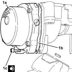
1. Place the vacuum unit (1a), complete with gasket (1b), back in its housing and secure it tightening the bolts (1c) to the recommended torque.
| Fastening | Component | Ø | Value (daNm) | |
|---|---|---|---|---|
| 1c |
Remove the cylinder head from the supporting tools.
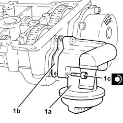
1. Place the engine oil filler (1a), complete with gasket (1b), back in its housing and secure it tightening the bolts (1c) to the recommended torque.
| Fastening | Component | Ø | Value (daNm) | |
|---|---|---|---|---|
| 1c |
Remove the support tool, complete with upper cylinder head from the vice and separate them.
Parts & tools for this job For 2001 Fiat Stilo
- PARTEngine gasket setSearch: Fiat Stilo 2001 engine gasket set
- TOOLTorque wrenchSearch: 3/8 inch torque wrench
- TOOLFeeler gauge setSearch: feeler gauge set
Links open Amazon search results in a new tab. As an Amazon Associate I earn from qualifying purchases.