
Single cylinder head, removed - overhaul
- Make
- Fiat
- Model
- Stilo Factory Service Manual
- Year
- 2001–2007
- Section
- Cylinder head/s › Single cylinder head, removed - overhaul
Single cylinder head, removed - overhaul
Dismantling
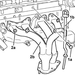
1. Undo the bolt (1a) and remove the engine oil dipstick guide pipe (1b).
2. Undo the nuts (2a) and remove the exhaust manifold (2b).
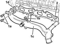
1. Undo the bolts (1a) and the nut (1b) and remov the water pump rigid inlet pipe (1c) complete with gasket.
2. Remove the exhaust manifold gasket.
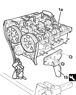
1. Position the cylinder head (1a) in the vice using the tool (1b).
| Name | Country | |
|---|---|---|
| 1b | Support | 1.860.470.000 |
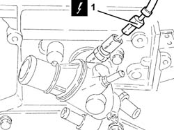
1. Disconnect the electrical connection from the engine coolant temperature sensor.
| Name | Connector | |
|---|---|---|
| 1 | Engine temperature sender unit | K36 |
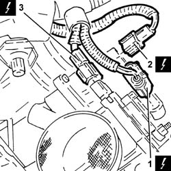
1. Disconnect the electrical connection from the butterfly position sensor.
| Name | Connector | |
|---|---|---|
| 1 | Integrated throttle body actuator | N75 |
2. Disconnect the electrical connection from the idle actuator.
| Name | Connector | |
|---|---|---|
| 2 | Integrated throttle body actuator | N75 |
3. Disconnect the electrical connection from the air flow meter.
| Name | Connector | |
|---|---|---|
| 3 | Air flow meter | K41 |
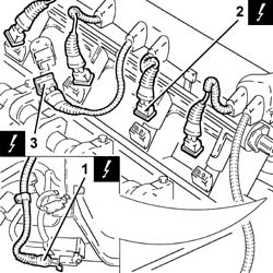
1. Disconnect the electrical connection from the fuel vapour solenoid valve.
| Name | Connector | |
|---|---|---|
| 1 | Fuel vapour recovery solenoid | L10 |
2. Disconnect the electrical connections from the injectors.
| Name | Connector | |
|---|---|---|
| 2 | Injector | N70 |
3. Disconnect the electrical connection from the variable valve timing electro-magnet.
| Name | Connector | |
|---|---|---|
| 3 | Timing variator actuator | N76 |
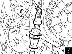
1. Disconnect the electrical connection for the timing sensor.
| Name | Connector | |
|---|---|---|
| 1 | Timing sensor | K47 |
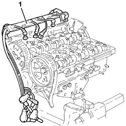
1. Remove the electrical wiring after having released it from the fastenings.
Disconnect the coolant outlet pipe for heating the butterfly casing from the thermostat.
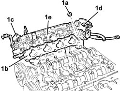
1. Undo the nuts (1a), then remove the inlet manifold (1b), complete with modular inlet manifold (1c), butterfly casing (1d) and fuel manifold pipe (1e).
Remove the inlet manifold gasket.
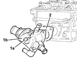
1. Undo the bolts (1a) and remove the thermostat (1b).
2. Remove the gasket.
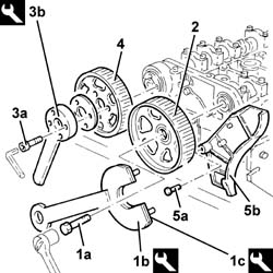
1. Undo the bolt (1a) for the timing driven pulley, exhaust side using the tools (1b) and (1c) for anti-torque.
| Name | Country | |
|---|---|---|
| 1b | Support for counter-torque | 1.860.831.000 |
| Name | Country | |
|---|---|---|
| 1c | Counter-torque | 1.860.848.000 |
2. Remove the timing driven pulley, exhaust side.
3. Undo the bolts (3a) for the inlet side camshaft pulley, using the tool (3b) for counter-torque.
| Name | Country | |
|---|---|---|
| 3b | Counter-torque | 1.860.856.000 |
4. Remove the timing driven pulley, inlet side.
5. Undo the bolts (5a) and remove the timing belt side protections (5b).
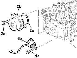
1. Undo the bolts (1a) and remove the cam angle sensor (1b).
2. Undo the bolts (2a) and remove the water pump (2b) complete with O-ring (2c).
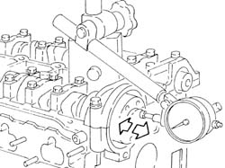
Check that the camshaft end float is within the recommended values using a dial gauge on a magnetic base.
| Measurement | Value | ||
|---|---|---|---|
| End float (mm) | 0.10 - 0.23 |
If the camshaft endfloat is not within the recommended values, when reassembling the cylinder head, replace the worn components.
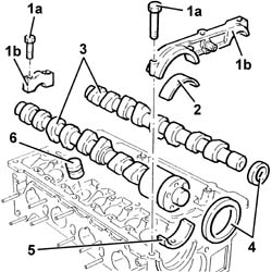
1. Undo the bolts (1a) and remove the camshaft caps (1b).
2. Remove the upper bearing shell for the front camshaft support, inlet side.
3. Remove the camshafts.
4. Remove the front camshaft oil seals.
5. Remove the lower bearing shell for the front camshaft support, inlet side.
6. Remove the hydraulic tappets.
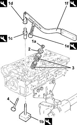
1. Remove the split collars (1a) using tools (1b), (1c), (1d), (1e) and (1f).
| Name | Country | |
|---|---|---|
| 1b | Valve retaining base | 1.860.786.000 |
| Name | Country | |
|---|---|---|
| 1c | Extension | 1.860.787.000 |
| Name | Country | |
|---|---|---|
| 1d | Lever hook | 1.860.788.000 |
| Name | Country | |
|---|---|---|
| 1e | Chamber | 1.860.840.000 |
| Name | Country | |
|---|---|---|
| 1f | Lever | 1.860.790.000 |
2. Remove the upper valve shim.
3. Remove the valve springs.
Remove the tools used for dismantling the valves.
4. Remove the valve.
Work in the same way to remove the remaining valves.
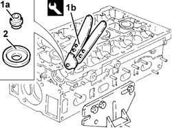
1. Remove the valve guide oil seal (1a) using the tool (1b).
| Name | Country | |
|---|---|---|
| 1b | Extractor | 1.860.989.000 |
2. Remove the lower valve shim.
1. Remove the valve guides (1a) using the tool (1b).
| Name | Country | |
|---|---|---|
| 1b | Drift | 1.860.395.000 |
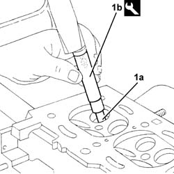
Reassembling
Clean the residues of the old gasket from the lower surface of the cylinder head.
Check that the planarity of the lower cylinder head surface is within the recommended values.
| Measurement | Value | ||
|---|---|---|---|
| Flatness of bottom surface (mm) | 0.1 |
If the planarity of the lower cylinder head surface is not within the recommended values, regrind the lower cylinder head surface without exceeding the minimum permissible height.
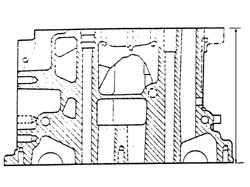
When the cylinder head has been refaced, check that the volume of the combustion chamber (with the valve and spark plugs temporarily fitted) is within the recommended values.
| Measurement | Value | ||
|---|---|---|---|
| Combustion chamber volume (c.c.) | 38.5 - 39.5 |
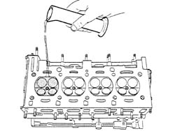
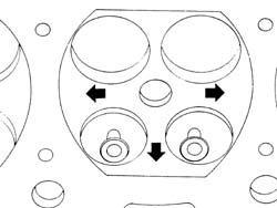
If the volume of the combustion chamber is not within the recommended figures, restore it by removing material from the inside of the combustion chamber at the points shown by the arrows.
De-carbonize the valves and check that the stem does not show signs of grooves.
Check that the diameter of the valve stems is within the recommended values; if this is not the case, replace the worn valves.
| Measurement | Value | ||
|---|---|---|---|
| Stem diameter (mm) | 6.975 - 6.990 |
| Measurement | Value | ||
|---|---|---|---|
| Stem diameter (mm) | 6.960 - 6.975 |
Check that the outer diameter of the hydraulic tappets is within the recommended values. if this is not the case, replace the worn parts.
| Measurement | Value | ||
|---|---|---|---|
| Outer diameter (mm) | 32.959 - 32.975 |
Check that the diameter of the hydraulic tappets in the cylinder head is within the recommended values; If this is not the case, replace the cylinder head.
| Measurement | Value | ||
|---|---|---|---|
| Diameter of hydraulic tappet seats (mm) | 33.000 - 33.025 |
Use a torque wrench to check that the valve spring specifications are within specified values; if this is not the case, replace parts that have yielded.
| Measurement | Value | ||
|---|---|---|---|
| Inner spring length (mm) | 29.5 | ||
| Check load (daN) | 9.61 - 10.6 | ||
| Measurement | Value | ||
|---|---|---|---|
| Inner spring length (mm) | 20.0 | ||
| Check load (daN) | 20.11 - 22.07 | ||
| Measurement | Value | ||
|---|---|---|---|
| Outer spring length (mm) | 34.0 | ||
| Check load (daN) | 27.07 - 29.43 | ||
| Measurement | Value | ||
|---|---|---|---|
| Outer spring length (mm) | 24.5 | ||
| Check load (daN) | 48.46 - 52.38 | ||
Check that the surfaces of the camshaft bearings and cams do not show signs of wear, grooves or seizing; if this is not the case, replace the camshafts.
Check that the cam journal diameters are within the recommended values; if this is not the case, replace the worn camshat.
| Measurement | Value | ||
|---|---|---|---|
| Journal diameter (mm) | 26.000 - 26.015 |
Check that the nominal lift of the camshaft cams is within the recommended values; if this is not the case, replace the worn camshat.
| Measurement | Value | ||
|---|---|---|---|
| Inlet shaft nominal cam lift (mm) | 9.0 |
| Measurement | Value | ||
|---|---|---|---|
| Nominal cam lift (mm) | 8.5 |
1. Fit the camshaft caps (1a) on the cylinder head and tighten the bolts (1b) to torque.
| Fastening | Component | Ø | Value (daNm) | |
|---|---|---|---|---|
| 1b | Bolt | CAMSHAFT SUPPORTS | M7 | Cylinder head side 1.3 ÷ 1.6 |
2. Check the diameter of the camshaft mounts is within specified values; If this is not the case, replace the cylinder head.
| Measurement | Value | ||
|---|---|---|---|
| 2 | Camshaft bearing diameter (mm) | 26.045 - 26.070 |
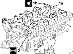
Check that the outer diameter of the valve guides to be fitted is within the recommended values.
| Measurement | Value | ||
|---|---|---|---|
| Outer diameter (mm) | 13.010 ÷ 13.030 | ||
| Oversize (mm) | 0.20 | ||
1. Fit the valve guide oil seals (1a) using the tool (1b).
| Name | Country | |
|---|---|---|
| 1b | Fitting tool | 1.860.812.000 |
Before fitting the new valve guides, heat the cylinder head in the oven to a temperature of 80 - 100 °C.
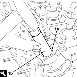
In the case of slight distortions suffered during fitting, ream the inner diameter of the valve guides to the recommended value.
| Measurement | Value | ||
|---|---|---|---|
| Inner diameter (bore) (mm) | 7.022 - 7.040 |
Regring the valve seats each time the valves or the valve guides are replaced.
1. Regrinding a valve seat with the cutter at 44° 30'.
Reduce the valve seat from above with the cutter at 20° and from below with the cutter at 75°, until the width of the band in contact with the valves is correct.
| Measurement | Value | ||
|---|---|---|---|
| Valve contact band width (mm) | ~ 2 |
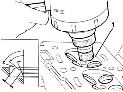
Measure the contact line of each valve against its seat; if the contact is not centred, make the appropriate reductions as described above.
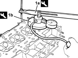
1. Temporarily fit the valves and the spark plugs and carry out the valve compression leakage test using tools (1a) and (1b).
| Name | Country | |
|---|---|---|
| 1a | Lever | 1.860.490.000 |
| Name | Country | |
|---|---|---|
| 1b | Test instrument | 1.895.868.000 |
Fit the lower valve shims back in their housings.
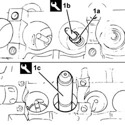
1. Fit the valve guide oil seals (1a) using the tools (1b) and (1c).
| Name | Country | |
|---|---|---|
| 1b | Drift | 1.860.813.000 |
| Name | Country | |
|---|---|---|
| 1c | Fitting tool | 1.860.454.000 |
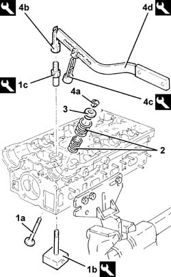
1. Fit the valve (1a) and support it using the tools (1b) and (1c).
| Name | Country | |
|---|---|---|
| 1b | Valve retaining base | 1.860.786.000 |
| Name | Country | |
|---|---|---|
| 1c | Extension | 1.860.787.000 |
2. Place the valve springs back in their housings.
3. Place the upper valve shim back in its housing.
4. Place the split cotters (4a) back in their housings using the tools (4b), (4c) and (4d).
| Name | Country | |
|---|---|---|
| 4b | Lever hook | 1.860.788.000 |
| Name | Country | |
|---|---|---|
| 4c | Chamber | 1.860.840.000 |
| Name | Country | |
|---|---|---|
| 4d | Lever | 1.860.790.000 |
Work in the same way when fitting the remaining valves.
Remove the tools used for refitting the valves.
Place the inlet side camshaft front support lower bearing shell back in its housing.
Place the camshafts back in their housings.
Place the inlet side camshaft front support upper bearing shell back in its housing.
1. Place the camshft caps (1a) back in their housings and secure them tightening the bolts (1b) to the recommended torque.
| Fastening | Component | Ø | Value (daNm) | |
|---|---|---|---|---|
| 1b | Bolt | CAMSHAFT SUPPORTS | M7 | Cylinder head side 1.3 ÷ 1.6 |
2. Place the water pump (2a), complete with O-Ring (2b), back in its housing and secure it tightening the bolts (2c) to the recommended torque.
| Fastening | Component | Ø | Value (daNm) | |
|---|---|---|---|---|
| 2c | Bolt | COOLANT PUMP | M8 | (Cylinder head side) 2.1 ÷ 2.6 |
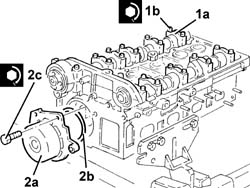
Place the cam angle sensor back in its housing and fix it using the bolt.
1. Fit the front camshaft oil seal, exhaust side (1a) using the tool (1b).
| Name | Country | |
|---|---|---|
| 1b | Fitting tool | 1.860.824.000 |
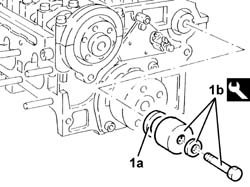
1. Fit the front camshaft oil seal, inlet side (1a) using the tool (1b).
| Name | Country | |
|---|---|---|
| 1b | Fitting tool | 1.860.844.000 |
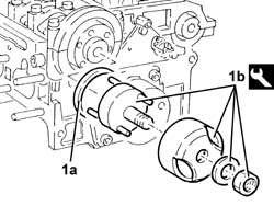
Place the timing belt side guards back in their housings and secure them using the bolts.
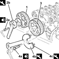
1. Place the inlet side timing driven pulley back in its housing.
2. Tighten th bolts (2a) for the inlet side timing driven pulley to the recommended torque using the tool (2b) for counter-torque.
| Fastening | Component | Ø | Value (daNm) | |
|---|---|---|---|---|
| 2a | Bolt | TIMING GEAR DRIVEN PULLEYS | M6 | (Inlet/camshaft side) 0.8 - 1.0 |
| Name | Country | |
|---|---|---|
| 2b | Counter-torque | 1.860.856.000 |
3. Place the exhust side timing driven pulley back in its housing.
4. Tighten the bolt (4a) for the exhaust side timing driven pulley to the recommended torque using the tools (4b) and (4c) for counter-torque.
| Fastening | Component | Ø | Value (daNm) | |
|---|---|---|---|---|
| 4a | Bolt | TIMING GEAR DRIVEN PULLEYS | M12 | (Exhaust camshaft side) 10.2 - 12.6 |
| Name | Country | |
|---|---|---|
| 4b | Support for counter-torque | 1.860.831.000 |
| Name | Country | |
|---|---|---|
| 4c | Counter-torque | 1.860.848.000 |
Place the thermostat, complete with gasket, back in its housing and fix it tightening the bolts to the recommended torque.
| Fastening | Component | Ø | Value (daNm) | |
|---|---|---|---|---|
| Bolt | THERMOSTAT | M8 | (Cylinder head side) 2.1- 2.6 |
Refit the inlet manifold gasket.
Place the inlet manifold, complete with modular inlet manifold, butterfly casing and fuel manifold pipe back in its housing, then secure it tightening the bolts and the nuts to the recommended torque.
| Fastening | Component | Ø | Value (daNm) | |
|---|---|---|---|---|
| Nut | INLET MANIFOLD | M8 | (Cylinder head side) 2.1- 2.6 |
Connect the coolant outlet pipe for heating the butterfly casing to the thermostat.
Place the electrical wiring back in its seating and fix it to the bands.
Connect the timing sensor electrical connection.
Connect the electrical connection to the variable valve timing electro-magnet.
Connect the electrical connections to the injectors.
Connect the electrical connection to the fuel vapour solenoid valve.
Connect the electrical connection to the air flow meter.
Connect the electrical connection to the idle actuator.
Connect the electrical connection to the butterfly position sensor.
Connect the electrical connection to the engine coolant temperature sensor.
Remove the cylinder head from the vice and place the support tool back in its housing.
| Name | Country | |
|---|---|---|
| Support | 1.860.470.000 |
Place a new exhaust manifold gasket in the housing.
Place the water pump rigid inlet pipe, complete with gasket, back in its housing and secure it using the nut and the bolts.
| Fastening | Component | Ø | Value (daNm) | |
|---|---|---|---|---|
| Bolt | COOLANT PUMP RIGID INLET PIPE | M6 | Cylinder head side 0.8 - 1.0 |
| Fastening | Component | Ø | Value (daNm) | |
|---|---|---|---|---|
| Nut | COOLANT PUMP RIGID INLET PIPE | M8 | Cylinder head side 2.1 - 2.6 |
Place the exhaust manifold back in its housing and fix it tightening the nuts to the recommended torque.
| Fastening | Component | Ø | Value (daNm) | |
|---|---|---|---|---|
| Nut | EXHAUST MANIFOLD/S | M8 | (Cylinder head side) 2.5 |
Place the guide and engine oil dipstick assembly back in its housing and fix it using the bolt.
Parts & tools for this job For 2001 Fiat Stilo
- PARTEngine gasket setSearch: Fiat Stilo 2001 engine gasket set
- TOOLTorque wrenchSearch: 3/8 inch torque wrench
- TOOLFeeler gauge setSearch: feeler gauge set
Links open Amazon search results in a new tab. As an Amazon Associate I earn from qualifying purchases.