
Thermostat unit - r+r
- Make
- Fiat
- Model
- Stilo Factory Service Manual
- Year
- 2001–2007
- Section
- Engine cooling › Thermostat unit - r+r
Thermostat unit - r+r
Removing
- 5530B52 Battery DRIP TRAY/SUPPORT - R.R.
Position a suitable container to collect the coolant.
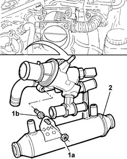
1. Remove retaining collar (1a) and disconnect coolant entry sleeve (1b) on the thermostat side
2. Undo retaining screws (2a) and remove thermostat assembly (2b)
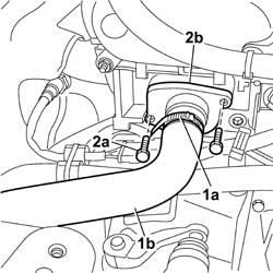
Removing
Place the vehicle on a ramp.
- 5530B56 BATTERY DRIP TRAY COVER - R.R.
Disconnect the battery negative terminal.
| Name | Connector | |
|---|---|---|
| Battery | A1 |
- 7055B54 under-engine guard - r r
- 1048A32 sleeve from air cleaner to intake manifold - r + r
Removing
- 1048A32 sleeve from air cleaner to intake manifold - r + r
Place a container under the vehicle to collect the engine coolant.
1. Disconnect the electrical connection from the engine temperature sensor.
| Name | Connector | |
|---|---|---|
| 1 | Engine temperature sender unit | K36 |
2. Disconnect the coolant hoses from the thermostat.
3. Undo the retaining bolts.
4. Remove the thermostat from the cylinder head.
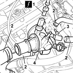
Removing
Place the car on a lift.
Raise the car.
- 7055B54 under-engine guard - r r
Lower the vehicle.
- 5530B56 BATTERY DRIP TRAY COVER - R.R.
Ensure that the ignition key is in the OFF position, then disconnect the negative battery terminal.
- 5530B52 Battery DRIP TRAY/SUPPORT - R.R.
- 1016A40 ignition coil cover on cylinder head- r+r
- 1056B82 injection/ignition system e.c.u. (one) - r + r
- 1048A31 RIGID PIPE between air filter and intake manifold - R.R.
Undo the fixing bolt and move the heater return pipe mounting bracket aside.
1. Disconnect the electrical connection from the engine coolant temperature sensor.
| Name | Connector | |
|---|---|---|
| 1 | Engine temperature sender unit | K36 |
2. Disconnect the upper coolant inlet hose to the radiator from the thermostat.
Recover the coolant which comes out in a suitable container.
3. Disconnect the coolant supply pipe to the engine oil heat exchanger from the thermostat.
4. Disconnect the supply pipe to the engine coolant tank from the thermostat.
5. Undo the bolts fixing the thermostat to the cylinder head.
6. Disconnect the supply pipe to the heater from the thermostat.
Break the collar connecting the thermostat to the heater return pipe.
7. Disconnect the water return pipe to the water pump from the thermostat.
8. Remove the thermostat unit with o-rings.
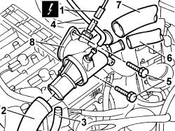
Removing
Place the car on a ramp.
- 1016A10 sound-proofing cover - r + r
- 5530B56 BATTERY DRIP TRAY COVER - R.R.
- 5530B52 Battery DRIP TRAY/SUPPORT - R.R.
Raise the lift.
- 7055B54 under-engine guard - r r
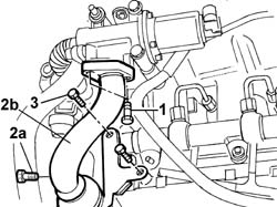
1. Undo the upper and lower bolts securing the exhaust gas recirculation pipe to the exhaust manifold.
2. Undo the fixing bolt (2a) and remove the section (2b) of the exhaust gas recirculation pipe.
Refitting
Tighten the bolts securing the thermostat assembly to torque.
| Fastening | Component | Ø | Value (daNm) | |
|---|---|---|---|---|
| Bolt | THERMOSTAT CONTAINER | M6 | 1 |
Connect the coolant intake pipe and secure it with the appropriate retaining collar
- 5530B52 Battery DRIP TRAY/SUPPORT - R.R.
- 0010T21 coolant check density and top up if necessary
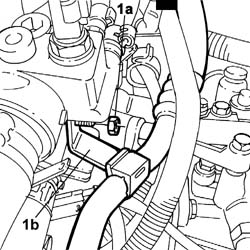
1. Undo the nut (1a) and move aside the bracket (1b) securing the pipe from the compressor to the expansion valve.
Refitting
Fit the thermostat in its seat on the cylinder head.
Tighten the fixing bolts to torque.
| Fastening | Component | Ø | Value (daNm) | |
|---|---|---|---|---|
| Bolt | THERMOSTAT CONTAINER | M8 | 2.5 |
Connect the coolant hoses to the thermostat.
Connect the electrical connection to the engine temperature sensor.
| Name | Connector | |
|---|---|---|
| Engine temperature sender unit | K36 |
- 1048A32 sleeve from air cleaner to intake manifold - r + r
Refitting
Fit the thermostat assembly with o-rings.
Connect, to the thermostat, the return pipe to the pump.
Connect, to the thermostat, the supply pipe to the heater.
Use a new band to join both pipes to the heater.
Tighten the bolts securing the thermostat to the cylinder head to torque.
| Fastening | Component | Ø | Value (daNm) | |
|---|---|---|---|---|
| Bolt | THERMOSTAT | M8 | 2.5 |
Connect, to the thermostat, the coolant supply pipe to the coolant tank.
Connect, to the thermostat, the coolant supply pipe to the engine oil heat exchanger.
Connect, to the thermostat, the upper coolant inlet hose to the radiator.
Connect the electrical connection to the engine coolant temperature sensor.
| Name | Connector | |
|---|---|---|
| Engine temperature sender unit | K36 |
Position the heater return pipe mounting bracket and tighten the fixing bolt.
- 1048A31 RIGID PIPE between air filter and intake manifold - R.R.
- 1056B82 injection/ignition system e.c.u. (one) - r + r
- 1016A40 ignition coil cover on cylinder head- r+r
- 5530B52 Battery DRIP TRAY/SUPPORT - R.R.
Connect the battery negative terminal.
- 5530B56 BATTERY DRIP TRAY COVER - R.R.
Raise the car.
- 7055B54 under-engine guard - r r
Lower the vehicle.
Remove the vehicle from the ramp.
Position a container suitable for collecting the engine coolant.
Disconnect the lower radiator hose and drain the engine coolant.
Remove the container used for collecting the coolant.
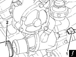
1. Disconnect the upper radiator pipe from the thermostat.
2. Disconnect the water temperature sensor electrical connection.
| Name | Connector | |
|---|---|---|
| 2 | Engine temperature sender unit | K36 |
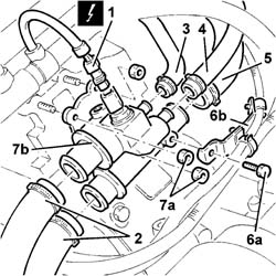
1. Disconnect the electrical connection from the engine coolant temperature sensor.
| Name | Connector | |
|---|---|---|
| 1 | Engine temperature sender unit | K36 |
2. Disconnect the coolant supply and return hoses to the radiator from the thermostat.
Recover the coolant which comes out in a suitable container.
3. Disconnect the coolant return pipe to the tank from the thermostat.
4. Disconnect the coolant supply pipe to the heater from the thermostat.
5. Disconnect the coolant supply hose to the water pump from the thermostat.
6. Undo the bolt (6a) and move the wiring mounting bracket (6b).
7. Undo the nuts (7a) and remove the thermostat (7b), complete with gasket.
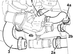
1. Disconnect the recirculation pipe (1a) to the reservoir and the two supply and return pipes (1b) and (2c) to the heater from the thermostat.
2. Disconnect the pipe from the thermostat and from the EGR exhaust gas supply pipe, then remove it.
3. Disconnect the supply pipe from the thermostat to the water pump rigid inlet pipe.
4. Disconnect the pipe (4a) and (4b) from the exhaust gas supply pipe.
Refitting
Place the thermostat, complete with gasket, back in its housing and fix it tightening the nuts to the recommended torque.
| Fastening | Component | Ø | Value (daNm) | |
|---|---|---|---|---|
| Nut | THERMOSTAT | M8 | (Cylinder head side) 2,1 - 2,6 |
Place the wiring mounting bracket back in its housing and fix it to the thermostat using the bolt.
Connect the coolant return hose to the water pump to the thermostat.
Connect the coolant supply pipe to the heater to the thermostat.
Connect the coolant return pipe to the tank to the thermostat.
Connect the coolant supply and return hoses to the radiator from the thermostat.
Connect the electrical connection to the engine coolant temperature sensor.
| Name | Connector | |
|---|---|---|
| 1 | Engine temperature sender unit | K36 |
- 1048A32 sleeve from air cleaner to intake manifold - r + r
- 7055B54 under-engine guard - r r
Connect the battery's negative terminal.
| Name | Connector | |
|---|---|---|
| Battery | A1 |
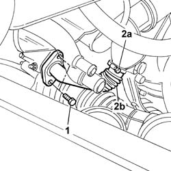
1. Undo the bolts fixing the exhaust gas supply pipe to the EGR solenoid valve.
2. Undo the bolt (2a) and remove the rear section which supplies exhaust gas to the EGR (2b).
3. Undo the bolts fixing the exhaust gas supply pipe mounting bracket to the cylinder head.
Position the pipe from the compressor to the expansion valve and secure it with its nut.
1. Undo the nut fixing the exhaust gas supply pipe to the thermostat stud.
2. Undo the bolts fixing the thermostat to the cylinder head.
3. Remove the thermostat unit together with the centre section of the EGR exhaust gas supply pipe.
- 5530B56 BATTERY DRIP TRAY COVER - R.R.
Top up the engine cooling system with specified coolant.
| Type | Component | Name | Qty. | |
|---|---|---|---|---|
| Fluid | THERMOSTAT | PARAFLU 11 |
Remove the car from the ramp.
Refitting
Fit the thermostat / EGR exhaust gas supply pipe centre section assembly.
Tighten the bolts fixing the thermostat to torque.
| Fastening | Component | Ø | Value (daNm) | |
|---|---|---|---|---|
| Bolt | THERMOSTAT | M8 | 2.5 |
Tighten the nut fixing the exhaust gas supply pipe to the thermostat stud/bolt.
Tighten the bolts fixing the exhaust gas supply pipe to the cylinder head.
Fit the front and rear sections of the exhaust gas supply pipe to the centre section, securing them using the bands.
Tighten the bolts fixing the front section of the exhaust gas supply pipe to the exhaust manifold.
Tighten the bolts fixing the rear section of the exhaust gas supply pipe to the EGR valve.
Connect the electrical connection for the water temperature sensor.
| Name | Connector | |
|---|---|---|
| Engine temperature sender unit | K36 |
Connect the flexible rubber pipes disconnected from the thermostat.
- 5530B52 Battery DRIP TRAY/SUPPORT - R.R.
- 5530B56 BATTERY DRIP TRAY COVER - R.R.
- 1016A10 sound-proofing cover - r + r
- 7055B54 under-engine guard - r r
Remove the vehicle from the ramp.
Parts & tools for this job For 2001 Fiat Stilo
- FLUIDCoolantSearch: Fiat coolant antifreeze
- PARTThermostatSearch: Fiat Stilo 2001 thermostat
- TOOLCooling system pressure testerSearch: cooling system pressure tester
Links open Amazon search results in a new tab. As an Amazon Associate I earn from qualifying purchases.