| Installation Special Tool(s) | | Support bar, Engine 303-290A (21-140A) | | | Adapter for 303-290A 303-290-01 (21-140-01) | | | Adapter for 303-290A 303-290-02 (21-140-02) | | | Adapter for 303-290A 303-290-03A (21-140-03A) | | | Adapter for 303-290A 303-290-08 (21-140-08) | General Equipment Retaining straps Transmission jack Installation All vehicles NOTE:The location of the engine mounts and the engine support insulators are given looking from the automatic transaxle to the engine. | | -
CAUTION:The torque converter must remain at the correct installation depth throughout the whole installation procedure. NOTE:The torque converter hub must engage fully in the oil pump drive gear. Check the installation depth of the torque converter. - Lay a steel straight edge on the automatic transaxle flange.
- Check the installation depth between the transaxle flange and the torque converter centering spigot for the correct clearance: 15 mm.
| | | -
Apply high temperature grease thinly to the torque converter centering spigot. | | | -
NOTE:Make sure that the dowels are installed correctly. NOTE:The torque converter studs must be aligned with the engine drive plate holes before any transaxle to engine bolts are installed. | | | -
NOTE:Flange bolts have different lengths. Install the flange bolts. - M10 x 90.
- M10 x 35 and M8 x 12.
- M10 x 35.
- M10 x 60.
- M10 x 50.
| | | -
NOTE:Install new torque converter retaining nuts. Install the torque converter to the flexplate (four nuts). | | | -
Install the torque converter cover (if equipped). | | | -
Install the rear engine mount bracket. | | | -
Install the rear engine mount. | | | -
Remove the special tools. | | | -
CAUTION:Support the halfshaft. The inner joint must not be bent more than 18 degrees. The outer joint must not be bent more than 45 degrees. CAUTION:Do not damage the halfshaft oil seal. CAUTION:Make sure the snap ring is correctly seated. NOTE:Install a new snap ring. Attach the left-hand halfshaft to the transaxle. | | | -
CAUTION:Support the halfshaft. The inner joint must not be bent more than 18 degrees. The outer joint must not be bent more than 45 degrees. CAUTION:Do not damage the halfshaft oil seal. Attach the right-hand halfshaft and intermediate shaft assembly to the transaxle. | | | -
NOTE:Install a new intermediate shaft bearing cap and locknuts. Install the intermediate shaft bearing cap. | | | -
CAUTION:Install a new nut. CAUTION:Make sure the heat shield is installed to prevent damage to the ball joint. Attach the lower arm to the wheel knuckle on both sides. - Attach the suspension arm ball joint.
- Install the bolt.
| | | -
Install the engine support insulator. | | | -
Attach the selector lever cable to the transaxle. - Attach the selector lever cable to the bracket.
- Attach the selector lever cable.
| | | -
Connect the output shaft speed (OSS) sensor electrical connector. | | | -
CAUTION:Using an open end wrench, prevent the fluid pipe adapter from turning. Attach the oil cooler pipes to the transaxle. | | | -
CAUTION:Install a new nut. Install the left-hand tie-rod end. | | | -
Install the starter motor bolts. | | | -
Connect the front exhaust pipe and the three-way catalytic converter (TWC). | | | -
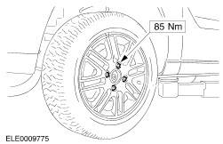
Install the left-hand front wheel. | | | -
Install the transaxle fluid level indicator tube. | | | -
Install the transaxle fluid level indicator tube bracket. | | | -
Connect the electrical connectors and install the selector lever cable to the automatic transaxle selector lever. - Transmission range (TR) sensor electrical connector.
- Automatic transaxle electrical connector.
| | | -
Connect the turbine shaft speed (TSS) sensor electrical connector. | | | -
Install the air cleaner intake pipe. | | | -
Connect the exhaust gas recirculation (EGR) vacuum line to the EGR valve. | | | -
Tighten the strut and spring assembly top mount nuts on both sides. | | | -
Install the battery tray. - Attach the wiring harness.
- Install in the bolts.
- Connect the electrical connector .
| | | -
Install the air cleaner housing. - Press the air cleaner housing into the rubber bushes.
- Connect the intake hose.
- Install the positive crankcase ventilation (PCV) hose.
- Install the mass air flow (MAF) sensor electrical connector.
| | | -
Check the transmission fluid level after the road test and correct as necessary. | | | -
Check the engine and cooling system for leaks (visual inspection). | Vehicles with front and rear power windows |