
Schematic layout of the air conditioning system
- Make
- Land Rover
- Model
- Defender 90 Workshop Manual (NAS)
- Section
- Description and operation › Schematic layout of the air conditioning system
Air conditioningSchematic layout of the air conditioning system · page 1 of 2
SCHEMATIC LAYOUT OF THE AIR CONDITIONING SYSTEM
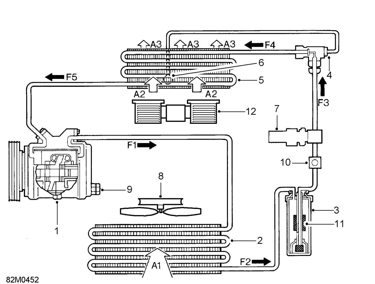
- Compressor A1 Ambient air flow through condenser
- Condenser A2 Recirclatory air flow through fan and evaporator
- Receiver/drier A3 Cooled air flow to vehicle interior
- Thermostatic expansion valve F1 High pressure high temperature refrigerant
- Evaporator
- Capillary tube F2 High pressure slightly subcooled refrigerant
- Trinary pressure switch
- Condenser cooling fan - single only F3 High pressure slightly subcooled refrigerant
- Compressor high pressure relief valve
- Sight glass - refrigerant
- Drying agent - receiver/drier F4 Low pressure low temperature mixed liquid and
- Blower motor F5 Low pressure slightly super heated refrigerant
vapour
liquid
liquid with moisture, vapour bubbles and foreign matter removed
vapour
vapour
Parts & tools for this job For Land Rover Defender
- TOOLA/C manifold gauge setSearch: AC manifold gauge set
- TOOLUV leak detection kitSearch: AC UV leak detection kit
- PARTCabin filterSearch: Land Rover Defender cabin filter
Links open Amazon search results in a new tab. As an Amazon Associate I earn from qualifying purchases.