
Front suspension (Front suspension): Description and operation
- Make
- Land Rover
- Model
- Defender 90 Workshop Manual (NAS)
- Section
- Description and operation › Front suspension
also uses ferrule rubber bush mountings at both axle DESCRIPTION and chassis locations.
The front suspension design allows maximum wheel Two rubber bearing bushes, with retaining straps, travel and axle articulation providing good ground secure the rear of the anti-roll bar to the chassis clearance without loss of traction or directional mountings, while bushed links support the front of the stability. A wheel speed sensor is attached to each bar to the front axle. swivel housing with a reluctor ring on the constant velocity joints. The input from the wheel sensors are Conventional long travel coil springs and hydraulic used by the engine management ECM for ’Off-road shock absorbers are used to control body movement detection’. in all conditions. The shock absorbers are secured to fabricated towers which are bolted to the chassis. The Long radius arms are fitted to the front axle and upper and lower fixings use a single location stud with provide maximum axle articulation which is vital for off flexible rubber bushes, support washers and securing road performance. The radius arms are secured to nuts. Retaining plates are used to secure the coil fabricated mounting brackets welded to the front axle. springs to the fabricated towers and axle mountings. Flexible rubber bushes are used on a stem end joint to secure the rear of the radius arms to mountings on Rubber bump stops are fitted underneath the chassis, the chassis cross member. adjacent to the front road springs, and prevent possible damage that could occur should there be A panhard rod, which ensures that the front axle excessive axle to chassis movement. remains centrally located, is fitted transversely and
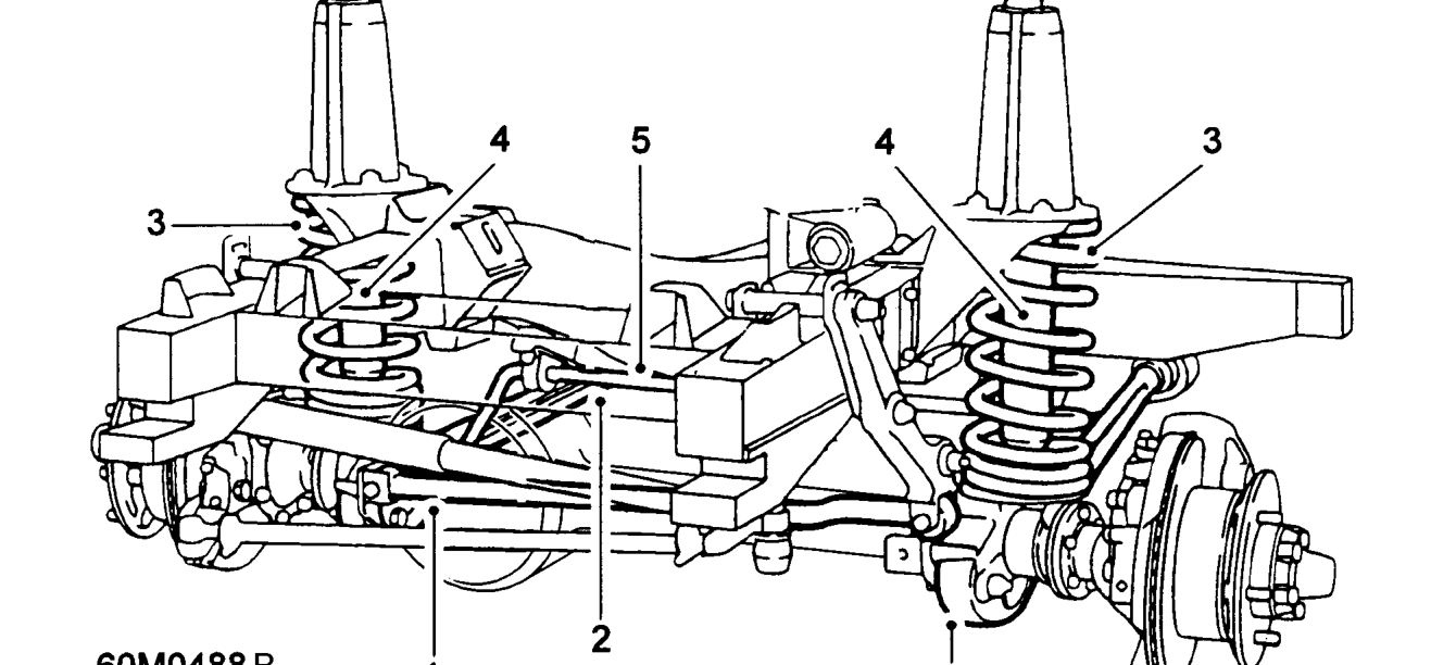
Front suspension
- Panhard rod
- Radius arms
- Coil springs
- Shock absorber
- Anti-roll [sway] bar
Parts & tools for this job For Land Rover Defender
- TOOLCoil spring compressorSearch: coil spring compressor
- TOOLBall joint separatorSearch: ball joint separator
- PARTFront shock absorbersSearch: Land Rover Defender front shock absorbers
Links open Amazon search results in a new tab. As an Amazon Associate I earn from qualifying purchases.