
Steering lock stops front wheel alignment
- Make
- Land Rover
- Model
- Defender 90 Workshop Manual (NAS)
- Section
- Adjustment › Steering lock stops front wheel alignment
SteeringSteering lock stops front wheel alignment
STEERING LOCK STOPS FRONT WHEEL ALIGNMENT
Service repair no - 57.65.03 Service repair no - 57.65.01
Check Checking Toe-out dimensions
- Measure clearance between tyre wall and radius arm at full lock. This must be not less than 20 mm, 0.79 in. equipment is described below. No Adjustment is provided for castor, camber or swivel pin inclinations.
- NOTE: Recognised front wheel alignment
- and tracking equipment should be used
- for this operation. Only the use of basic
- Set vehicle on level ground with road wheels positioned straight ahead.
- Push vehicle back and forwards to settle linkage.
- Set up the equipment to manufactures instructions and check alignment as advised by equipment supplier.
Adjust
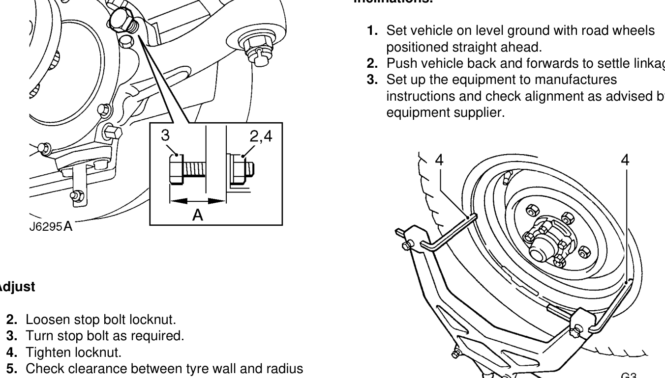
- Loosen stop bolt locknut.
- Turn stop bolt as required.
- Tighten locknut.
- Check clearance between tyre wall and radius arm on each lock.
- NOTE: Alternatively lock stop adjustment
- may be carried out using following
- procedure.
Check
- Measure stop bolt protrusion ’A’, this must be 59.7 mm, 2.35 in.
Adjust
- Loosen stop bolt locknut.
- Turn stop bolt as required.
- Tighten locknut.
- Check wheel position at full lock.
- Position trammel probes on inner face of wheel, not the rims, if the latter are damaged.
- Measure toe-out at horizontal centre-line of wheels.
- Check tightness of clamp bolt fixings. Tighten to 14 Nm, 10lbf ft.
Parts & tools for this job For Land Rover Defender
- TOOLTie rod end toolSearch: tie rod end puller
- TOOLBall joint separatorSearch: ball joint separator
- FLUIDPower steering fluidSearch: Land Rover power steering fluid
Links open Amazon search results in a new tab. As an Amazon Associate I earn from qualifying purchases.