
19 - FUEL SYSTEM - LAND ROVER V8: DESCRIPTION AND OPERATION (page 18 of 32)
- Make
- Land Rover
- Model
- Range Rover P38
19
FUEL SYSTEM
NEW RANGE ROVER
48
DESCRIPTION AND OPERATION
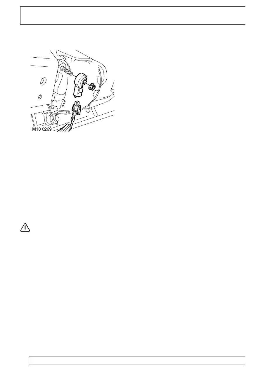
Knock Sensors (KS) - from 99MY
The ECM utilises active knock control, which serves to
prevent engine damage through pre-ignition or
detonation. Knock control is effective under all
operating conditions, enabling the engine to operate
without additional safety margins.
Two knock sensors are used, one mounted each side
of the cylinder block between the two centre cylinders
of each bank. Each sensor has two wires; a signal
wire providing input to the ECM and a ground
(screen). Each of the sensors monitor the ’knock’ from
four cylinders (Cylinder No’s: 1, 3, 5 & 7 and Cylinder
No’s: 2, 4, 6 & 8).
CAUTION: The connector and sensor
terminals are gold plated to provide good
conductivity and resistance to corrosion
and high temperatures. Be careful not to damage
terminals if probing with test equipment.
The knock sensors consist of piezo-ceramic crystals
that oscillate to create a voltage signal. During
pre-ignition, the frequency of crystal oscillation
increases which alters the signal output to the ECM.
The signal is processed by comparing it to signal
profiles contained in memory which indicate a
pre-ignition condition. If pre-ignition conditions are
evident, the ECM retards the ignition on that cylinder
for a number of cycles. The ignition timing gradually
reverts to its original setting.
The ignition system is calibrated to run on 95 RON
Premium fuel for optimum fuel economy and
performance characteristics. The system can also
function satisfactorily with 91 RON Regular fuel. If the
vehicle is refuelled with a lower grade of fuel some
audible detonation may be heard until the system
adaptions are complete for the new fuel grade.
If a knock sensor should fail, the following symptoms
may be observed:
•
Possible rough running
•
Reduction in engine performance
A knock sensor failure is likely to occur for the
following reasons:
•
Sensor open circuit
•
Short circuit to vehicle supply or ground
•
Faulty component
•
Loose sensor - incorrectly torqued
If knock control is disabled, a default "safe ignition
map" is used.
If a knock sensor should fail, the following fault codes
will be generated by the ECM diagnostics, which can
be retrieved by Testbook:
•
P0327 - (LH bank signal less than the threshold
value determined from the ECM model above
2200 rpm)
•
P0328 - (LH bank signal greater than the
threshold value determined from the ECM model
above 2200 rpm)
•
P0332 - (RH bank signal less than the threshold
value determined from the ECM model above
2200 rpm)
•
P0333 - (RH bank signal greater than the
threshold value determined from the ECM model
above 2200 rpm)
Noise induced on the battery supply line could be
misinterpreted as a knock signal and cause a
maximum knock fault. A maximum fault could be
caused by a short circuit to the battery supply or in the
case of extreme mechanical engine noise / piston
slap. A minimum fault is usually due to an open circuit.
Parts & tools for this job For Land Rover Range Rover
- PARTFuel filterSearch: Land Rover Range Rover fuel filter
- TOOLFuel pressure test kitSearch: fuel pressure test kit
- TOOLFuel line disconnect toolSearch: fuel line disconnect tool
Links open Amazon search results in a new tab. As an Amazon Associate I earn from qualifying purchases.