
8.6. Bleeding the Brake System
- Make
- Peugeot
- Model
- J5 Pocket Mechanic, 1.8 and 2.0 petrol
- Year
- 1987–1994
- Section
- Bleeding the brake system › 8.6. Bleeding the Brake System
A clevis pin is used to connect the push rod to the brake pedal. The vacuum hose (1) in Fig. 8.16 must be disconnected.
Repairs are restricted to replacing the servo unit filters at the push rod end. To do this, pull back the rubber boot, remove the retainer and remove the old filters with a pointed tool. The new filters must be cut with a pair of scissors from the outside towards the inside and then pushed over the push rod. Refit the remaining parts in reverse order.
If the servo unit shown in Fig. 8.18 is fitted, adjust the length of the push rod if the servo unit has been replaced. The push rod can be adjusted after slackening of the locknut. To make sure which of the two dimensions applies, measure the length of the old push rod which will be approximately within the two ranges already given.
The push rod (5) must also be adjusted on a servo unit with one chamber. To find the dimension, place a straight edge over the end face of the unit and measure the distance to the tip of the push rod (5). The push rod must be 0.3 to 0.5 mm below the end face. If this is not the case, slacken the locknut and turn the push rod with a pair of pliers.
The installation of the servo unit is a reversal of the removal procedure.
8.6. Bleeding the Brake System
Bleeding of the brake system is required when the brake circuit has been opened or air has entered the system, for example if the fluid level in the reservoir has dropped too far.
The vehicle must be placed on secure chassis stands. Before commencing the bleeding operation clean the areas around the bleeder screws and the filler cap of the reservoir.
If only one wheel brake cylinder or one caliper has been disconnected it may be sufficient to bleed just the circuit connected to this brake unit. To find out which one it is study Fig. 8.1 and follow the brake lines.
Otherwise start the bleeding at the rear brakes, then the upper bleed screws of the front brakes, followed by the lower bleed screws. You will need a helper, as the fluid level in the reservoir must be continuously observed, as it must not drop below the min. level and of course, to operate the brake pedal. Proceed as follows:
- Remove the rubber dust cap from the bleeder screw and push a transparent bleeder hose over the bleeder screw. Bleeder hoses are available from accessory shops. Hold the other end of the hose into a glass jar, filled with some
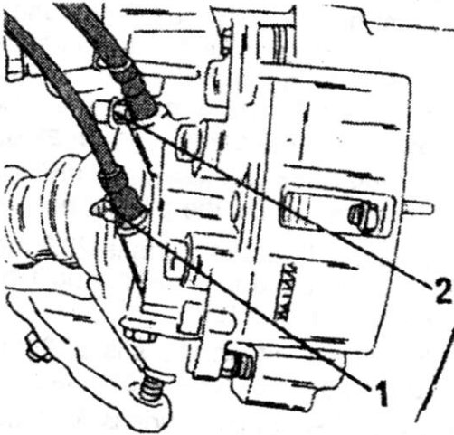
- upper bleed screw
- lower bleed screw
Parts & tools for this job For 1987 Peugeot J5
- PARTBrake padsSearch: Peugeot J5 1987 brake pads
- TOOLBrake bleeder kitSearch: one man brake bleeder kit
- FLUIDBrake fluidSearch: brake fluid
Links open Amazon search results in a new tab. As an Amazon Associate I earn from qualifying purchases.