
5.5. Reaction Strut
- Make
- Peugeot
- Model
- J5 Pocket Mechanic, 1.8 and 2.0 petrol
- Year
- 1987–1994
- Section
- Reaction strut › 5.5. Reaction Strut
Front axle and suspension5.5. Reaction Strut
- Clamp the steering knuckle into a vice as shown in Fig. 5.12, attach the dial gauge holder and place the stylus onto the end of the bolt as shown in the illustration. Set the dial gauge to "Zero".
- Grip the end of the bolt (1) and move it to and fro, at the same time observing the dial gauge reading. The indication should be between 0.025 and 0.10 mm.
- If the clearance is not within the limits, shims (7) in Fig. 5.10 must be increased or decreased in their thickness. Shims are available in different sizes.
- Remove the used tools and take out the wheel bearings, if shims must be replaced.
- Grease the bearing (5) in Fig. 5.10 and drive it into the steering knuckle. Fit the grease seal (6) into the steering knuckle until the outside is flash.
- Place the wheel hub with the flange onto the press table and drive the steering knuckle and the inserted bearing over the hub. A piece of tube of suitable diameter must be used. The tube must be placed against the inner bearing race. Drive the bearing fully over the hub.
- Place the selected shim, the bearing spacer and the second shim into the inside of the steering knuckle.
- Fit the well greased inner bearing race (2) into the steering knuckle, using a suitable piece of tube and fit a new oil seal (1). A sectional view of the final assembly stage is shown in Fig. 5.13.
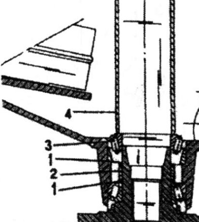
- Adjusting shim
- Bearing spacer
- Inner wheel bearing
- Fitting tube
5.5. Reaction Strut
The reaction strut can be seen in Fig. 5.8 in fitted position. A reaction strut must, for example, be removed if the castor requires adjustment, as the adjusting shims at the rear of the strut may have to be replaced.
Remove a strut bar as follows:
- Remove the nut at the rear of the strut and withdraw the fitted parts.
- At the bottom of the suspension arm remove the nut securing the strut bar and remove the strut from the suspension arm and the chassis bracket. Note the installation order of all parts.
Installation is a reversal of the removal procedure. Shims removed during removal must be fitted to the original position. Tighten the strut to the specified torque. There may be no need to check the castor adjustment, unless the bar, the rubber bushes or the washers have been replaced.
If the front wheel geometry must be checked refer to the relevant section in the next Chapter.
Parts & tools for this job For 1987 Peugeot J5
- TOOLCoil spring compressorSearch: coil spring compressor
- TOOLBall joint separatorSearch: ball joint separator
- PARTFront shock absorbersSearch: Peugeot J5 1987 front shock absorbers
Links open Amazon search results in a new tab. As an Amazon Associate I earn from qualifying purchases.