
6.6. Power-Assisted Steering
- Make
- Peugeot
- Model
- J5 Pocket Mechanic, 1.8 and 2.0 petrol
- Year
- 1987–1994
- Section
- Power-assisted steering › 6.6. Power-Assisted Steering
Steering6.6. Power-Assisted Steering
toe-in is set to 0.5 ± 1.0 mm, i.e. the front wheels have toe-in. Measure as follows:
- Check the tyre pressures and correct as necessary.
- Place the vehicle on level ground and turn the front wheels into the straight-ahead position.
- Place the tracking gauge with the pins against the wheel rims (level of wheel hubs) and set the gauge to "Zero". Mark the contact points with chalk or a spot of paint.
- Push the vehicle forward by half a turn of the wheels, i.e. the marked spot must now be at the rear, again level with the wheel hubs.
- Push the tracking gauge underneath the vehicle and place one pin against the marked spot. The pin on the other side will most probably not reach the rim. Unlock the moveable pin and pull it towards the outside until it can be placed against the rim. Lock the pin in position.
- Remove the tracking gauge and read off the measurement. The indication should be 0.5 mm higher or within the tolerance of 1.0 mm more or less.
- If an adjustment is necessary, slacken the locknuts at the inside of the two track rod ball joints und turn the track rods by the same amount on both sides. Note that there must be a gap of at least 2.0 mm (0.08 in.) between the track rod ball joint and the locknut face. Make sure that the rubber gaiters cannot twist when the rods are turned. Slacken and re-tighten the gaiter clamp bands if necessary.
- Finally tighten the two locknuts to 6.0 kgm (43.5 ft.lb.). The track rods must be held against rotation.
6.6. Power-Assisted Steering
6.6.0. REMOVAL AND INSTALLATION
- Disconnect the battery.
- From the inside of the passenger compartment remove the cover for the steering universal joint and lift it up.
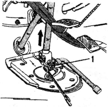
Fig. 6.9. — After slackening the nut and clamp bolt (1) and removing the bolt, push the steering shaft in the direction of the arrow to disengage it from the steering pinion. Tie the shaft to one side.
- Remove the clamp bolt and the nut securing the universal joint as shown in Fig. 6.9. The clamp bolt is driven out and the steering shaft pulled upwards until the joint if free of the steering pinion. Secure the shaft with a piece of wire in this position to have it out of the way.
- Remove the union nut immediately behind the steering pinion. The nut connects the fluid return pipe.
- Jack up the front end of the vehicle and place chassis stands underneath the body. The wheels can be removed to cre-
Parts & tools for this job For 1987 Peugeot J5
- TOOLTie rod end toolSearch: tie rod end puller
- TOOLBall joint separatorSearch: ball joint separator
- FLUIDPower steering fluidSearch: Peugeot power steering fluid
Links open Amazon search results in a new tab. As an Amazon Associate I earn from qualifying purchases.