
Suspension lower arm assembly
- Make
- Rover
- Model
- 200 Workshop Manual
- Year
- 1995–1999
- Section
- Repairs › Suspension lower arm assembly
Front suspensionSuspension lower arm assembly
SUSPENSION LOWER ARM ASSEMBLY
Service repair no - 60.35.02
Remove
- Raise front of vehicle.
WARNING: Support on safety stands.
- Remove front road wheel.
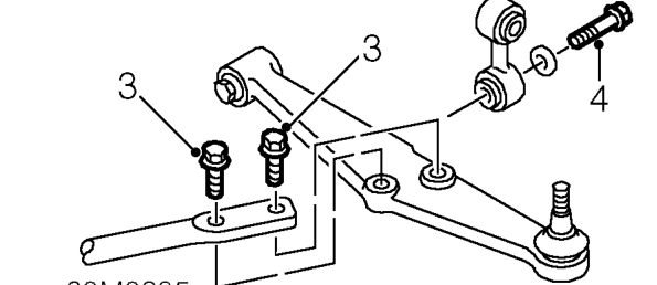
- Remove 2 bolts securing tie rod to lower arm.
- Remove bolt securing anti-roll bar link to lower arm.
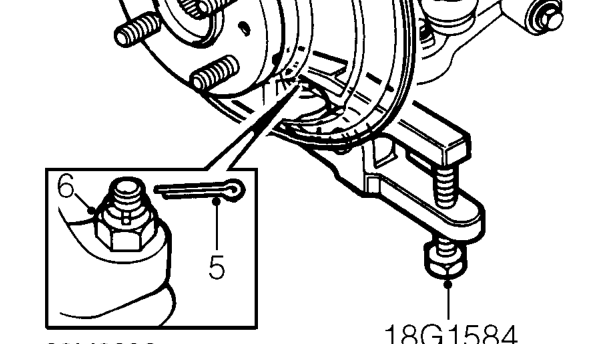
- Remove and discard split pin from castellated nut securing front hub to lower arm.
- Loosen castellated nut securing hub to lower arm, until flush with the end of the joint. If necessary apply penetrating oil to joint.
- Break taper joint using tool 18G 1584.
CAUTION: Be careful not to damage the rubber boot on lower ball joint.
- Remove nut from lower ball joint and release lower arm from front hub.
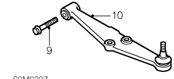
- Remove bolt securing lower arm to rear beam.
- Remove lower arm.
Refit
- Clean mating surfaces of lower arm and rear beam.
- Clean lower arm ball joint.
- Position lower arm to rear beam, fit bolt but do not tighten.
- Locate front hub on lower arm ball joint.
- Fit castellated nut securing hub to lower arm and tighten to 55 Nm, then align next slot in nut with split pin hole.
- Secure castellated nut with new split pin.
- Align tie rod to lower arm, fit bolts and tighten to 80 Nm.
- Align anti-roll bar link to lower arm, fit bolt and tighten to 60 Nm.
- Tighten through bolt securing lower arm to rear beam to 45 Nm.
- Fit road wheel(s) and tighten nuts to correct torque. See INFORMATION, Torque wrench settings.
- Remove stand(s) and lower vehicle.
Parts & tools for this job For 1995 Rover 200
- TOOLCoil spring compressorSearch: coil spring compressor
- TOOLBall joint separatorSearch: ball joint separator
- PARTFront shock absorbersSearch: Rover 200 1995 front shock absorbers
Links open Amazon search results in a new tab. As an Amazon Associate I earn from qualifying purchases.