
Front Inner wing
- Make
- Rover
- Model
- 400 Body Repair Manual
- Year
- 1995–2000
- Section
- Sealing and corrosion protection › Front Inner wing
InformationFront Inner wing
Front Inner wing
The small triangular symbols indicate sealing locations
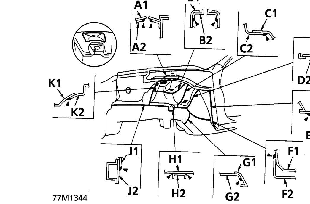
A 1 Spring housing, 2 Upper arm reinforcement B 1 Spring housing, 2 Upper arm reinforcement C 1 Housing extension, 2 Spring housing D 1 Dashboard lower, 2 Housing extension E 1 Inner lower, 2 Outer panel F 1 Dashboard lower, 2 Outrigger G 1 Outrigger, 2 Side frame H 1 Side frame, 2 Brake pipe bracket J 1 Spring housing, 2 Side frame K 1 Inner wing, 2 Spring housing
Parts & tools for this job For 1995 Rover 400
- TOOLTorque wrenchSearch: 3/8 inch torque wrench
- TOOLSocket setSearch: socket set metric
- BOOKHaynes manualSearch: Haynes manual Rover 400
Links open Amazon search results in a new tab. As an Amazon Associate I earn from qualifying purchases.