
Undercoating Diagram
- Make
- Rover
- Model
- 400 Body Repair Manual
- Year
- 1995–2000
- Section
- Sealing and corrosion protection › Undercoating Diagram
InformationUndercoating Diagram
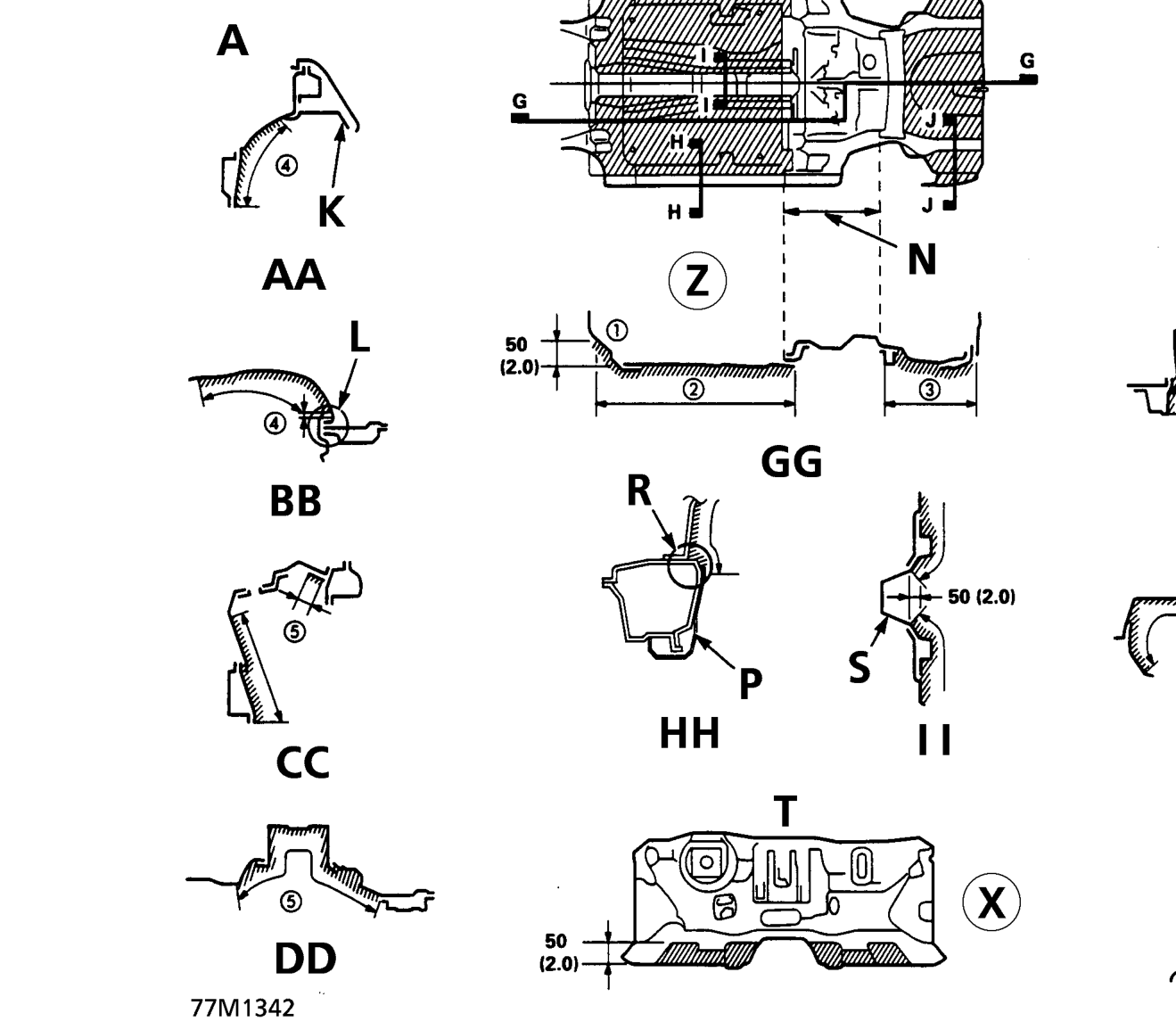
Undercoating Diagram
| No. | Coating Portion | Coating Area |
|---|---|---|
| 1 | Dashboard lower | Lower section from 50mm (2in) and entire length of the inner wing side |
| 2 | Front floor | Whole floor except floor tunnel area |
| 3 | Rear floor | Whole floor except fuel tank mounting area |
| 4 | Front inner wing | Except inner wing mounting area |
| 5 | Front spring housing | Except spring mounting surface |
| 6 | Rear inner wing | Whole inner wing |
| 7 | Rear spring housing | Except spring mounting surface |
- Coating thickness: 0.5mm (0.02 in) MIN. Shading indicates PVC coating areas.
- Coating thickness 1 mm (0.04 in) on jack-up bracket and floor and inner wing flange seams.
Parts & tools for this job For 1995 Rover 400
- TOOLTorque wrenchSearch: 3/8 inch torque wrench
- TOOLSocket setSearch: socket set metric
- BOOKHaynes manualSearch: Haynes manual Rover 400
Links open Amazon search results in a new tab. As an Amazon Associate I earn from qualifying purchases.