
Front suspension operation
- Make
- Rover
- Model
- 400 Workshop Manual
- Year
- 1995–2000
- Section
- Description and operation › Front suspension operation
FRONT SUSPENSION OPERATION
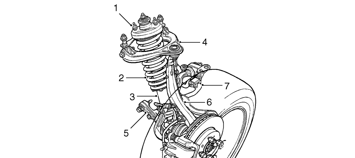
- Strut unit
- Coil spring
- Damper unit
- Upper arm - wishbone
The front suspension has been carefully developed to combine refinement with robustness.
The independent swivel hubs and knuckles are located at the top by a wishbone type upper arm and at the bottom by a transverse lower arm and radius arm assembly. The damper and spring units are located between the upper wishbones and attached to the lower arms by damper forks. The anti-roll bar is secured to the lower arms via rubber bushed links and is 18 mm diameter on 1.6 automatic models and 21 mm diameter on all other models.
- Transverse lower arm and radius arm
- Swivel hub
- Anti-roll bar
High longitudinal compliance gives cabin isolation, over high frequency large amplitude inputs (e.g. pot holes), on a par with much larger cars. Geometry is well controlled to give good handling responses. The suspension bump stop is at the top of the damper strut.
Parts & tools for this job For 1995 Rover 400
- TOOLCoil spring compressorSearch: coil spring compressor
- TOOLBall joint separatorSearch: ball joint separator
- PARTFront shock absorbersSearch: Rover 400 1995 front shock absorbers
Links open Amazon search results in a new tab. As an Amazon Associate I earn from qualifying purchases.