
Pump Pressure Check (page 3 of 3)
- Make
- Rover
- Model
- 600 Rover 600 Repair Manual - Volumes 1 and 2 - 2nd Edition
- Section
- Fault finding
SteeringPump Pressure Check · page 3 of 3
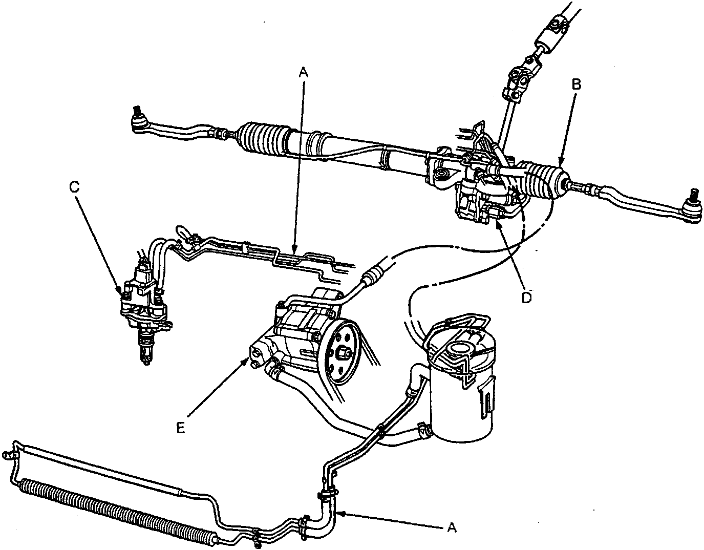
A Hoses and Pipes
Inspect hoses for damage, leaks, interference or twisting.
Inspect fluid lines for damage, rusting or leakage.
Inspect for leaks at hose and line joints or connections.
B Boot
Check for leaks.
C Power Steering Speed Sensor
Check for leaks at the inlet and outlet fittings.
D Gearbox and Valve Body Unit
Check for leaks at the mating surface and flare nut connections.
E Pump Assembly
Check for leaks at the pump seal, inlet and outlet fittings.
Parts & tools for this job For Rover 600
- TOOLTie rod end toolSearch: tie rod end puller
- TOOLBall joint separatorSearch: ball joint separator
- FLUIDPower steering fluidSearch: Rover power steering fluid
Links open Amazon search results in a new tab. As an Amazon Associate I earn from qualifying purchases.