
Steering Wheel (with SRS) Removal
- Make
- Rover
- Model
- 600 Rover 600 Repair Manual - Volumes 1 and 2 - 2nd Edition
- Section
- Repairs › Steering Wheel (with SRS) Removal
SteeringSteering Wheel (with SRS) Removal · page 1 of 2
Steering Wheel (with SRS) Removal
Airbag Removal
WARNING: Store a removed airbag assembly with the pad surface up, if the airbag is improperly stored face down accidental deployment could propel the unit with enough force to cause serious injury.
CAUTION:
- Before removing the steering wheel, align the front wheels straight ahead.
- Before beginning work related to the SRS system, turn the ignition switch off, disconnect the negative and positive battery cables, and wait three minutes.
- Do not install used SRS parts from another car. When repairing an SRS, use only new parts.
- Carefully inspect the airbag assembly before installing it. Do not install an airbag assembly that shows signs of being dropped or improperly handled, such as dents, cracks or deformation.
- Do not disassemble or tamper with the airbag assembly.
- Special bolts are necessary for installing the airbag assembly. Do not use other bolts.
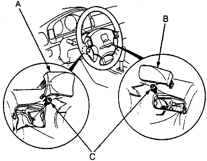
57M0082
- A Left Maintenance Lid
- B Right Maintenance Lid
- C TORX Bolts
- Turn the ignition switch off, then disconnect the negative and positive battery cables, and wait three minutes.
- Remove the left and right maintenance lids.
- Remove the left TORX bolt first (the safety switch will automatically turn off).
- Remove the right TORX bolt.
Note: Use a TORX T30 bit.
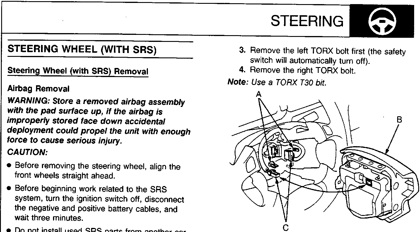
57M0083
- A Connector Locks
- B Airbag Assembly
- C SRS Wire Harness Connectors
- Remove the airbag assembly from the steering wheel.
- Pull out the connector locks, then disconnect the SRS wire harness connectors from the slip ring and airbag assembly.
Note: Dispose of the connector locks, they are not to be reused.
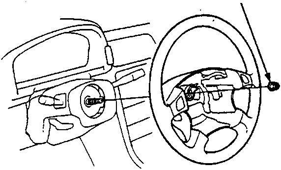
57M0084
- A Steering Wheel Nut
- Remove the steering wheel locknut.
- Remove the steering wheel by rocking it slightly from side-to-side as you pull steadily with both hands.
Parts & tools for this job For Rover 600
- TOOLTie rod end toolSearch: tie rod end puller
- TOOLBall joint separatorSearch: ball joint separator
- FLUIDPower steering fluidSearch: Rover power steering fluid
Links open Amazon search results in a new tab. As an Amazon Associate I earn from qualifying purchases.