
57M0167A
- Make
- Rover
- Model
- 600 Rover 600 Repair Manual - Volumes 1 and 2 - 2nd Edition
- Section
- Repairs › 57M0167A
Steering57M0167A · page 1 of 2
● Reinstall the 30 mm snap ring with its tapered side facing out.
Note: Snap rind ends must be aligned with the flat area.
- Reinstall the 30 mm snap ring with its tapered side facing out.
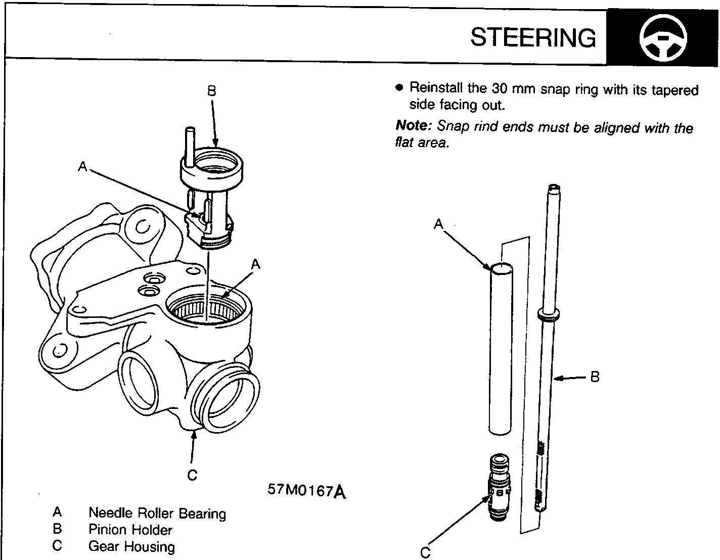
- Pack the needle roller bearing in the pinion holder with grease and install the pinion holder in the gear housing.
A Needle Roller Bearing
B Pinion Holder
C Gear Housing
57M0167A
● Pack the needle roller bearing in the pinion holder with grease and install the pinion holder in the gear housing.
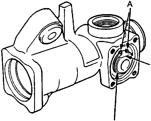
A Cylinder
B Steering Rack
C Seal Retainer
57M0169
22. Remove the cylinder and seal retainer from the steering rack. Inspect cylinder inner wall and rack surface for damage.
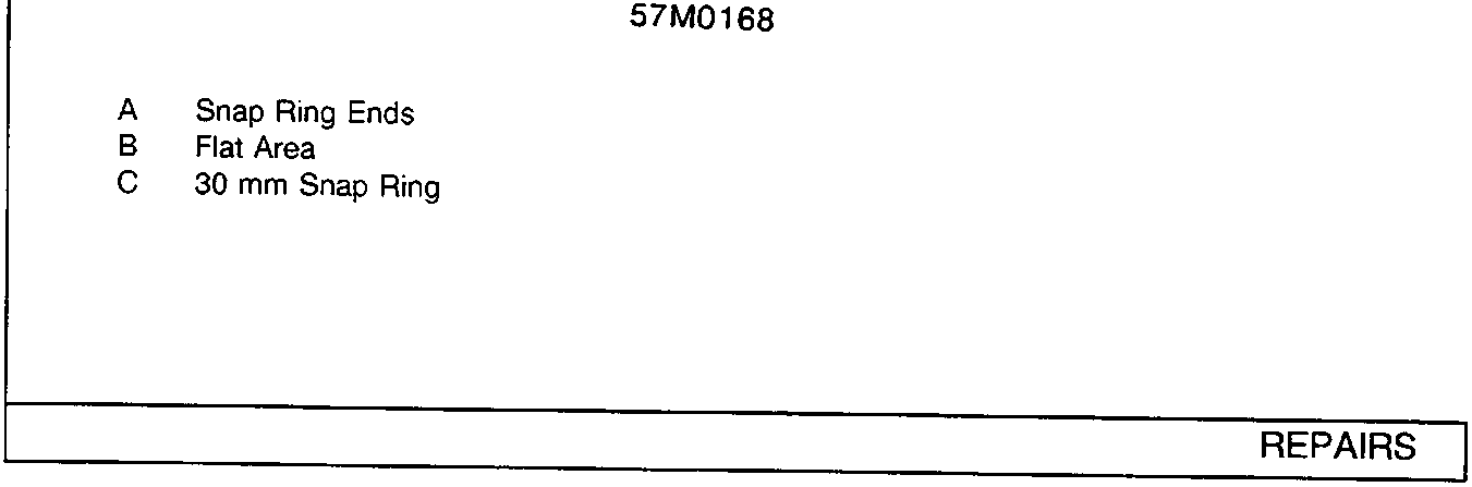
A Snap Ring Ends
B Flat Area
C 30 mm Snap Ring
57M0168
Parts & tools for this job For Rover 600
- TOOLTie rod end toolSearch: tie rod end puller
- TOOLBall joint separatorSearch: ball joint separator
- FLUIDPower steering fluidSearch: Rover power steering fluid
Links open Amazon search results in a new tab. As an Amazon Associate I earn from qualifying purchases.