
Original page
- Make
- Rover
- Model
- 600 Rover 600 Repair Manual - Volumes 1 and 2 - 2nd Edition
- Section
- Repairs › Original page
SteeringOriginal page · page 1 of 6
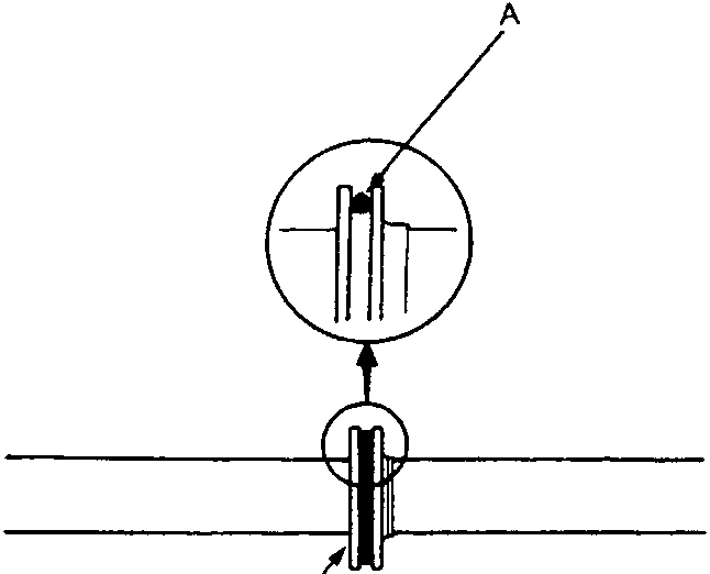
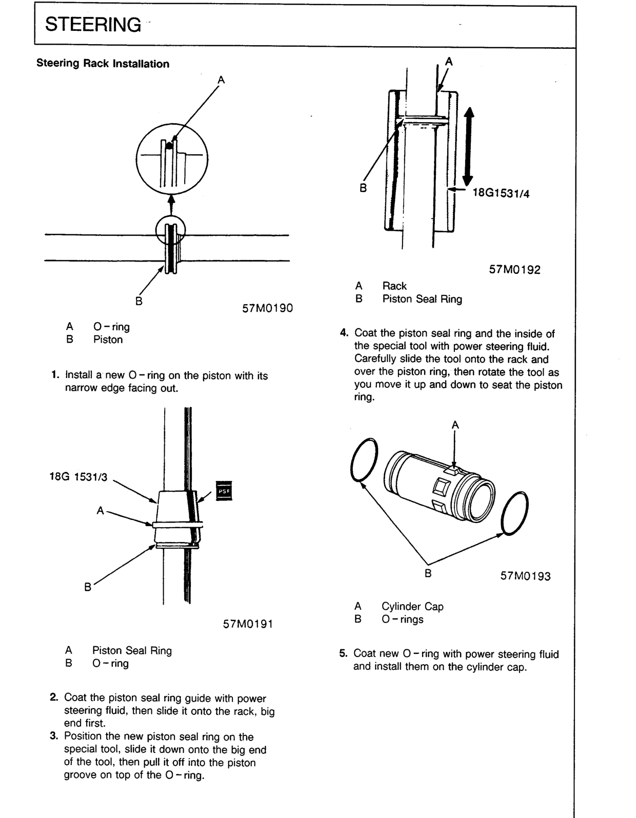
A O-ring
B Piston
- Install a new O-ring on the piston with its narrow edge facing out.
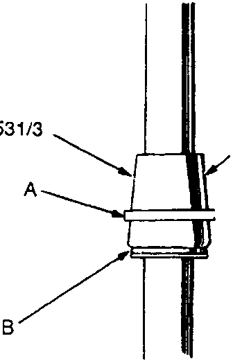
A Piston Seal Ring
B O-ring
- Coat the piston seal ring guide with power steering fluid, then slide it onto the rack, big end first.
- Position the new piston seal ring on the special tool, slide it down onto the big end of the tool, then pull it off into the piston groove on top of the O-ring.
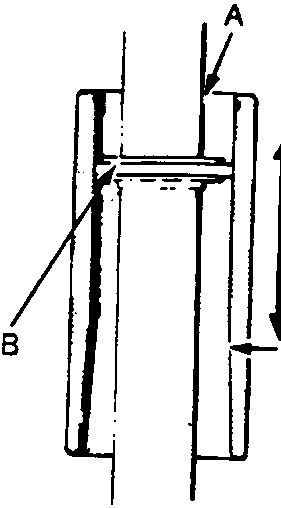
A Rack
B Piston Seal Ring
- Coat the piston seal ring and the inside of the special tool with power steering fluid. Carefully slide the tool onto the rack and over the piston ring, then rotate the tool as you move it up and down to seat the piston ring.
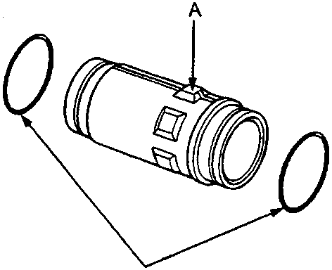
A Cylinder Cap
B O-rings
- Coat new O-ring with power steering fluid and install them on the cylinder cap.
Original page
Parts & tools for this job For Rover 600
- TOOLTie rod end toolSearch: tie rod end puller
- TOOLBall joint separatorSearch: ball joint separator
- FLUIDPower steering fluidSearch: Rover power steering fluid
Links open Amazon search results in a new tab. As an Amazon Associate I earn from qualifying purchases.