
Original page (page 5 of 6)
- Make
- Rover
- Model
- 600 Rover 600 Repair Manual - Volumes 1 and 2 - 2nd Edition
- Section
- Repairs
SteeringOriginal page · page 5 of 6
- Carefully position the cylinder on the gear housing and loosely install with four cylinder bolts.
CAUTION: Be careful not to damage the end seal in the cylinder housing.
- Remove the special tool from the steering rack.
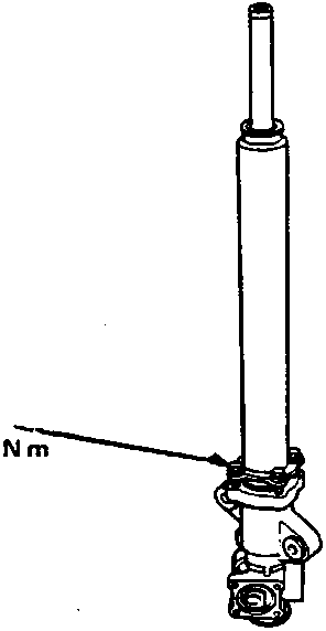
A Cylinder Bolts
- Insert the steering rack into the cylinder housing, being careful not to damage the steering rack sliding surface.
- Tighten the four cylinder bolts.
Note: Before tightening the bolts, make sure the mating surfaces of the cylinder and gear housings fit properly by pushing them together; hold them together while tightening the bolts.
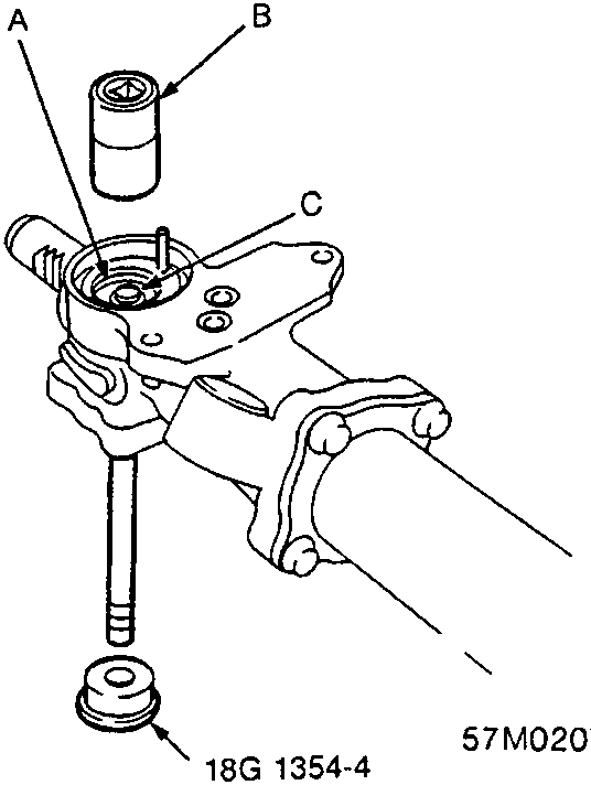
A Pinion Holder
B Socket
C Steering Pinion
- Install the steering pinion in the pinion holder.
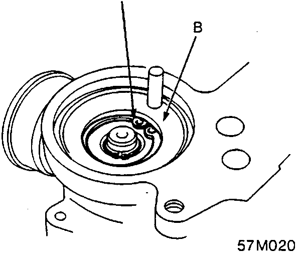
A 28 mm Snap Ring
B Pinion Holder
- Install the 28 mm snap ring securely in the pinion holder groove.
Note: Install the snap ring with its tapered side facing out.
Parts & tools for this job For Rover 600
- TOOLTie rod end toolSearch: tie rod end puller
- TOOLBall joint separatorSearch: ball joint separator
- FLUIDPower steering fluidSearch: Rover power steering fluid
Links open Amazon search results in a new tab. As an Amazon Associate I earn from qualifying purchases.