
Gear housing side
- Make
- Rover
- Model
- 600 Rover 600 Repair Manual - Volumes 1 and 2 - 2nd Edition
- Section
- Repairs › Gear housing side
SteeringGear housing side · page 1 of 4
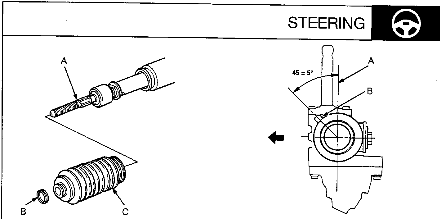
57M0217
- A Rack End
- B Tube Clamp
- C Boot
- Install the boots in the rack end with the tube clamps.
Note: Install the boots with the rack in the straight ahead position (i.e. right and left tie – rods are equal in length).
57M0219
Gear housing side
- A Offset Shaft Centre Line
- B Tube Joint (Left side boot)
- Install the boots so that the angle of the offset shaft centre line is as shown.
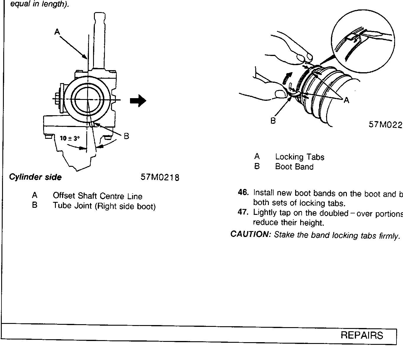
57M0218
Cylinder side
- A Offset Shaft Centre Line
- B Tube Joint (Right side boot)
57M0220
- A Locking Tabs
- B Boot Band
- Install new boot bands on the boot and bend both sets of locking tabs.
- Lightly tap on the doubled – over portions to reduce their height.
CAUTION: Stake the band locking tabs firmly.
Parts & tools for this job For Rover 600
- TOOLTie rod end toolSearch: tie rod end puller
- TOOLBall joint separatorSearch: ball joint separator
- FLUIDPower steering fluidSearch: Rover power steering fluid
Links open Amazon search results in a new tab. As an Amazon Associate I earn from qualifying purchases.