Workshop Manuals Factory service & repair Rover
01 Information02 General data03 Engine04 Engine management system – PGM-Fi05 Cooling system, manifold and exhaust06 Clutch07 Manual gearbox08 Automatic gearbox09 Drive shafts10 Differential – manual gearbox11 Differential – automatic gearbox12 Steering13 Suspension14 Brakes and ABS15 Brakes – ABS BY416 Body17 Heating and ventilation18 Electrical19 Supplementary restraint system (SRS)
Rover Rover 600 Repair Manual - Volumes 1 and 2 - 2nd Edition12 · Steering
12 · Steering & suspension

Gear housing side (page 3 of 4)

Make
Rover
Model
600 Rover 600 Repair Manual - Volumes 1 and 2 - 2nd Edition
Section
Repairs
SteeringGear housing side · page 3 of 4
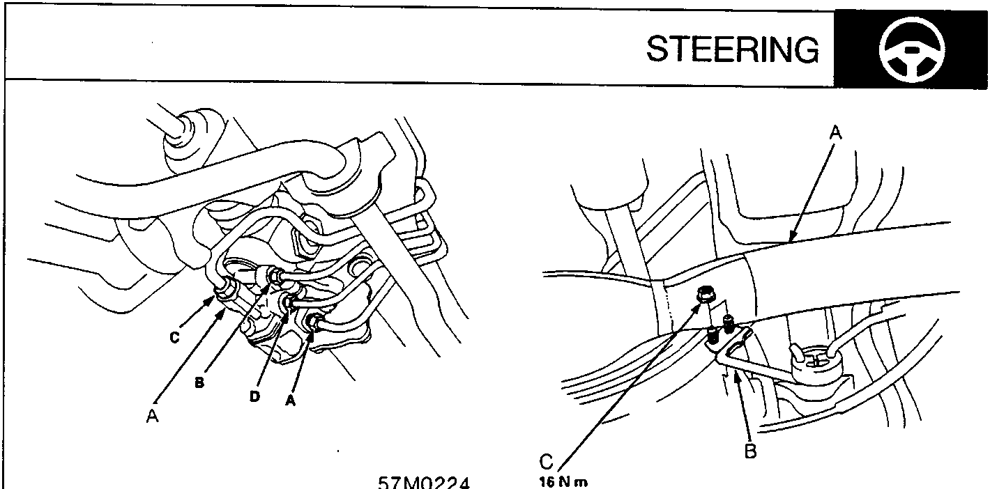
Diagram showing steering valve body unit connections and exhaust pipe bracket mounting points with callout labels A, B, C, D.
A Valve Body Unit 58. Connect the four lines to the valve body unit using flare nut spanners. A: From pump: 14 mm spanner 38 Nm B: To oil cooler: 12 mm spanner 13 Nm C: To reservoir: 17 mm spanner 29 Nm D: To power steering speed sensor: 12 mm spanner 13 Nm
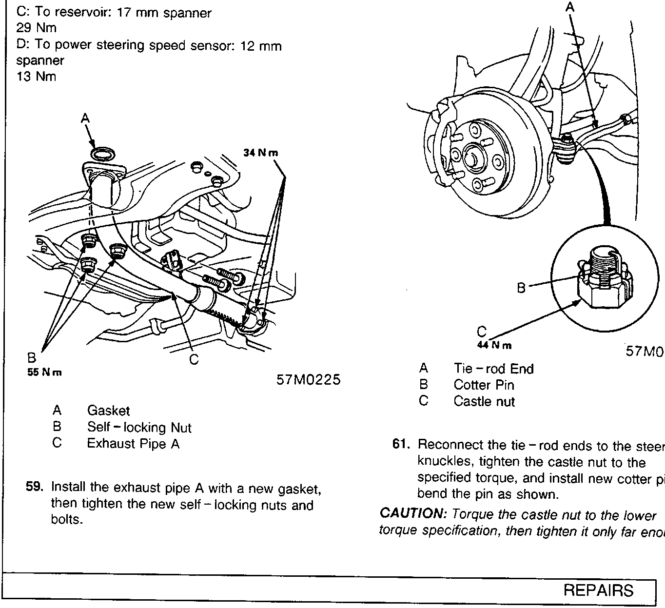
Diagram showing installation of exhaust pipe A with gasket and self-locking nuts on suspension component.
A Gasket B Self – locking Nut C Exhaust Pipe A 59. Install the exhaust pipe A with a new gasket, then tighten the new self – locking nuts and bolts. A Exhaust Pipe A B Pipe Bracket C Nut 60. Install the exhaust pipe bracket. A Tie – rod End B Cotter Pin C Castle nut 61. Reconnect the tie – rod ends to the steering knuckles, tighten the castle nut to the specified torque, and install new cotter pins; bend the pin as shown. CAUTION: Torque the castle nut to the lower torque specification, then tighten it only far enough

Parts & tools for this job For Rover 600

Links open Amazon search results in a new tab. As an Amazon Associate I earn from qualifying purchases.