
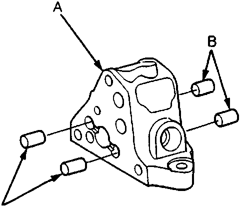
12. Check the plungers:
- Make
- Rover
- Model
- 600 Rover 600 Repair Manual - Volumes 1 and 2 - 2nd Edition
- Section
- Repairs › 12. Check the plungers:
Steering12. Check the plungers:
57M0180
- A Valve Body
- B Plungers
57M0181
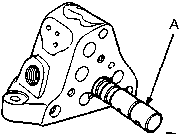
- A 4-way Valve
57M0182
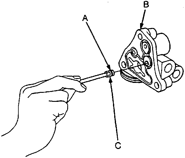
- A O-ring
- B Port Housing
- C Sensor Orifice
12. Check the plungers:
- Inspect their surface for scoring or scratches.
- Slip each plunger into the valve body and make sure it slides smoothly, without drag of side play.
If any plunger is damaged, replace it.
13. Check the 4-way valve:
- Inspect its surface for scoring and scratches.
- Slip it into the valve body and make sure it slides smoothly, without drag or side play.
Note: If the valve body is damaged, replace the valve body unit (valve body, pressure control valve, gain control valve, control valve) as an assembly.
14. Using a 3 mm drill bit, remove the sensor orifice and 3.4 mm O-ring. Discard the O-ring.
Original page
Parts & tools for this job For Rover 600
- TOOLTie rod end toolSearch: tie rod end puller
- TOOLBall joint separatorSearch: ball joint separator
- FLUIDPower steering fluidSearch: Rover power steering fluid
Links open Amazon search results in a new tab. As an Amazon Associate I earn from qualifying purchases.