
Original page
- Make
- Rover
- Model
- 600 Rover 600 Repair Manual - Volumes 1 and 2 - 2nd Edition
- Section
- Repairs › Original page
SteeringOriginal page
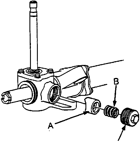
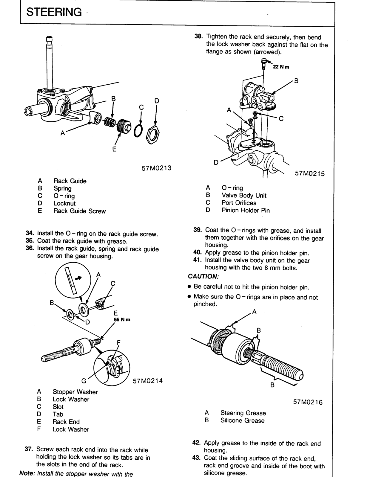
57M0213
- A Rack Guide
- B Spring
- C O-ring
- D Locknut
- E Rack Guide Screw
- Install the O-ring on the rack guide screw.
- Coat the rack guide with grease.
- Install the rack guide, spring and rack guide screw on the gear housing.
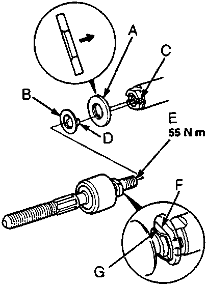
57M0214
- A Stopper Washer
- B Lock Washer
- C Slot
- D Tab
- E Rack End
- F Lock Washer
- Screw each rack end into the rack while holding the lock washer so its tabs are in the slots in the end of the rack.
Note: Install the stopper washer with the chamfered side facing out.
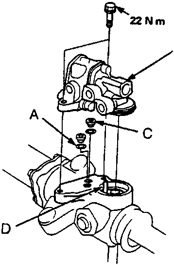
57M0215
- A O-ring
- B Valve Body Unit
- C Port Orifices
- D Pinion Holder Pin
- Tighten the rack end securely, then bend the lock washer back against the flat on the flange as shown (arrowed).
- Coat the O-rings with grease, and install them together with the orifices on the gear housing.
- Apply grease to the pinion holder pin.
- Install the valve body unit on the gear housing with the two 8 mm bolts.
CAUTION:
- Be careful not to hit the pinion holder pin.
- Make sure the O-rings are in place and not pinched.
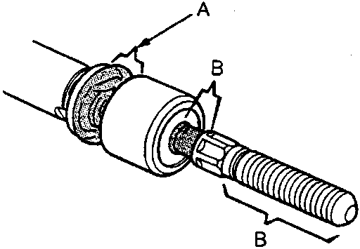
57M0216
- A Steering Grease
- B Silicone Grease
- Apply grease to the inside of the rack end housing.
- Coat the sliding surface of the rack end, rack end groove and inside of the boot with silicone grease.
Original page
Parts & tools for this job For Rover 600
- TOOLTie rod end toolSearch: tie rod end puller
- TOOLBall joint separatorSearch: ball joint separator
- FLUIDPower steering fluidSearch: Rover power steering fluid
Links open Amazon search results in a new tab. As an Amazon Associate I earn from qualifying purchases.