
Airbag installation
- Make
- Rover
- Model
- 600 Rover 600 Repair Manual - Volumes 1 and 2 - 2nd Edition
- Section
- Repairs › Airbag installation
SteeringAirbag installation
Airbag installation
CAUTION:
- Before installing the steering wheel, align the front wheels straight ahead.
- Be sure to install the harness wires so that they are not pinched or interfering with other car parts.
- Do not replace the original steering wheel with any other design, since it will make it impossible to properly install the airbag. (Only use genuine Rover replacement parts.)
- After reassembly, confirm that the wheels are still straight ahead and that steering wheel spoke angle is correct. If minor spoke angle adjustment is necessary, do so only by adjustment of the tie – rods, not by removing and repositioning the steering wheel.
WARNING: Confirm that the airbag assembly is securely attached to the steering wheel; otherwise, severe personal injury could result during airbag deployment.
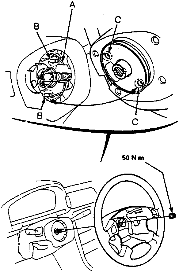
- A Slip Ring
- B Pin
- C Hole
- Install the steering wheel on the column shaft with a new steering wheel locknut.
Note: Align the holes on the steering wheel and pins on the slip ring.
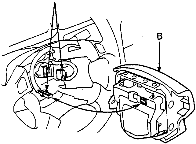
- A SRS Wire Harness Connectors
- B Airbag Assembly
- Connect the SRS wire harness connectors on the slip ring and airbag assembly.
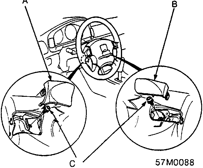
- A Left Maintenance Lid
- B Right Maintenance Lid
- C TORX bolts, 10 Nm
- Install the airbag assembly with new TORX bolts.
Note: Use a TORX T30 bit.
Parts & tools for this job For Rover 600
- TOOLOBD2 scanner with SRSSearch: OBD2 scanner ABS SRS
- TOOLTrim removal tool kitSearch: trim removal tool kit
Links open Amazon search results in a new tab. As an Amazon Associate I earn from qualifying purchases.