
57M0091
- Make
- Rover
- Model
- 600 Rover 600 Repair Manual - Volumes 1 and 2 - 2nd Edition
- Section
- Repairs › 57M0091
Steering57M0091
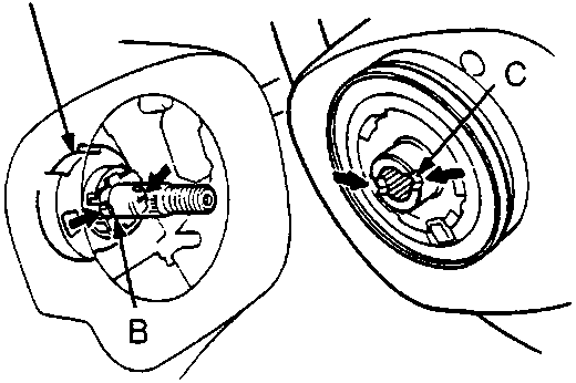
Note: If you can not obtain straight ahead position completely, turn the tie - rods equally to adjust the front wheel direction with the steering wheel straight ahead position. Adjust front toe, see SUSPENSION .
- Install the steering wheel with the front wheels straight in the ahead position.
Note: Align the slots on steering wheel and tabs on the turn signal cancelling sleeve.
- Make sure that the steering wheel is positioned correctly. Reposition the steering wheel if necessary.
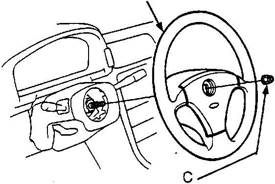
- Tighten the new steering wheel nut and install the badge.
- After installing the steering wheel, check the horn buttons for proper operation.
57M0091
- A Turn Signal Cancelling Sleeve
- B Tab
- C Slot
57M0092
- A Steering Wheel
- B Badge
- C Steering Wheel Nut
Parts & tools for this job For Rover 600
- TOOLTie rod end toolSearch: tie rod end puller
- TOOLBall joint separatorSearch: ball joint separator
- FLUIDPower steering fluidSearch: Rover power steering fluid
Links open Amazon search results in a new tab. As an Amazon Associate I earn from qualifying purchases.