
Steering Column Removal
- Make
- Rover
- Model
- 600 Rover 600 Repair Manual - Volumes 1 and 2 - 2nd Edition
- Section
- Repairs › Steering Column Removal
SteeringSteering Column Removal · page 1 of 5
Steering Column Removal
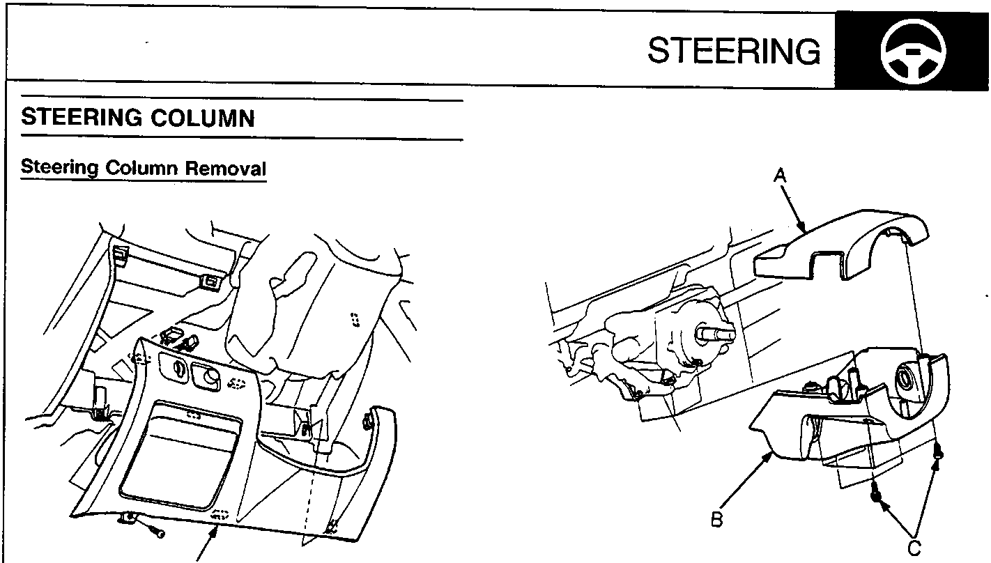
57M0093
A Lower Cover
57M0094
- A Upper Column Cover
- B Lower Column Cover
- C Screws
CAUTION:
- All SRS electrical wiring harnesses are covered with yellow outer insulation.
- Replace the entire affected SRS harness assembly if there is an open circuit or damage to the wiring.
- Remove the airbag assembly and steering wheel.
- Remove the lower cover.
- Remove the upper and lower column cover.
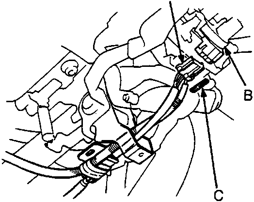
57M0095
- A SRS Main Harness Connector
- B Slip Ring
- C Connector Locks
- Pull out the connector lock, then disconnect the SRS main harness connector from the slip ring.
Note: Dispose of the connector locks, they are not to be reused.
Parts & tools for this job For Rover 600
- TOOLTie rod end toolSearch: tie rod end puller
- TOOLBall joint separatorSearch: ball joint separator
- FLUIDPower steering fluidSearch: Rover power steering fluid
Links open Amazon search results in a new tab. As an Amazon Associate I earn from qualifying purchases.