
Note:
- Make
- Rover
- Model
- 600 Rover 600 Repair Manual - Volumes 1 and 2 - 2nd Edition
- Section
- Repairs › Note:
SteeringNote: · page 1 of 6
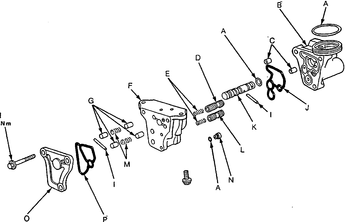
57M0183
| A | O-ring – replace | I | Roller |
| B | Port Housing | J | Port Seal |
| C | Dowel Pins | K | 4-way Valve |
| D | Pressure Control Valve | L | Gain Control Valve |
| E | Valve Springs | M | Return Springs |
| F | Valve Body | N | Sensor Orifice |
| G | Plungers | O | Valve Body Cap |
| H | 6 mm Flange Bolt | P | Cap Seal – replace |
Note:
- Clean the disassembled parts with a solvent and dry them with compressed air. Do not dip the rubber parts in a solvent.
- Always replace the O-rings and rubber seals with new ones before assembly.
- Apply recommended power steering fluid or steering grease to the parts indicated in the assembly procedures.
- Do not allow dust, dirt, or other foreign materials to enter the power steering system.
- If the valve body is damaged, replace the valve body unit (valve body, pressure control valve, gain control valve, 4-way valve) as an assembly.
Parts & tools for this job For Rover 600
- TOOLTie rod end toolSearch: tie rod end puller
- TOOLBall joint separatorSearch: ball joint separator
- FLUIDPower steering fluidSearch: Rover power steering fluid
Links open Amazon search results in a new tab. As an Amazon Associate I earn from qualifying purchases.