
Steering Column Removal (page 4 of 5)
- Make
- Rover
- Model
- 600 Rover 600 Repair Manual - Volumes 1 and 2 - 2nd Edition
- Section
- Repairs
SteeringSteering Column Removal · page 4 of 5
CAUTION:
- All SRS electrical wiring harnesses are covered with yellow outer insulation.
- Replace the entire affected SRS harness assembly if there is an open circuit or damage to the wiring.
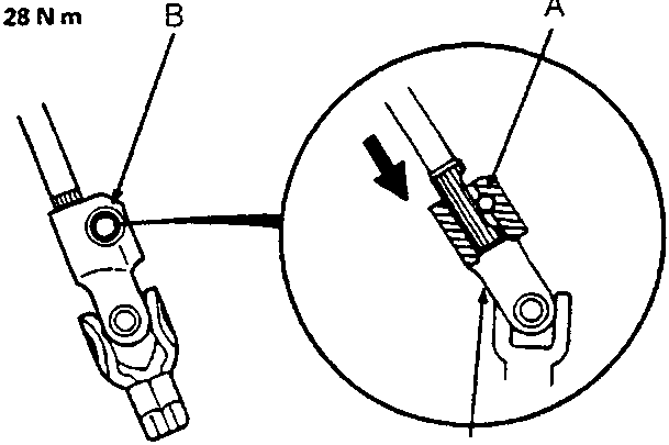
28 N m
- Slip the upper end of the steering joint onto the column shaft (line up the bolt hole with the flat on the shaft) and loosely install the upper steering joint bolt.
A Upper Steering Joint Bolt.
B Final torque – 28 NM
C Steering Joint
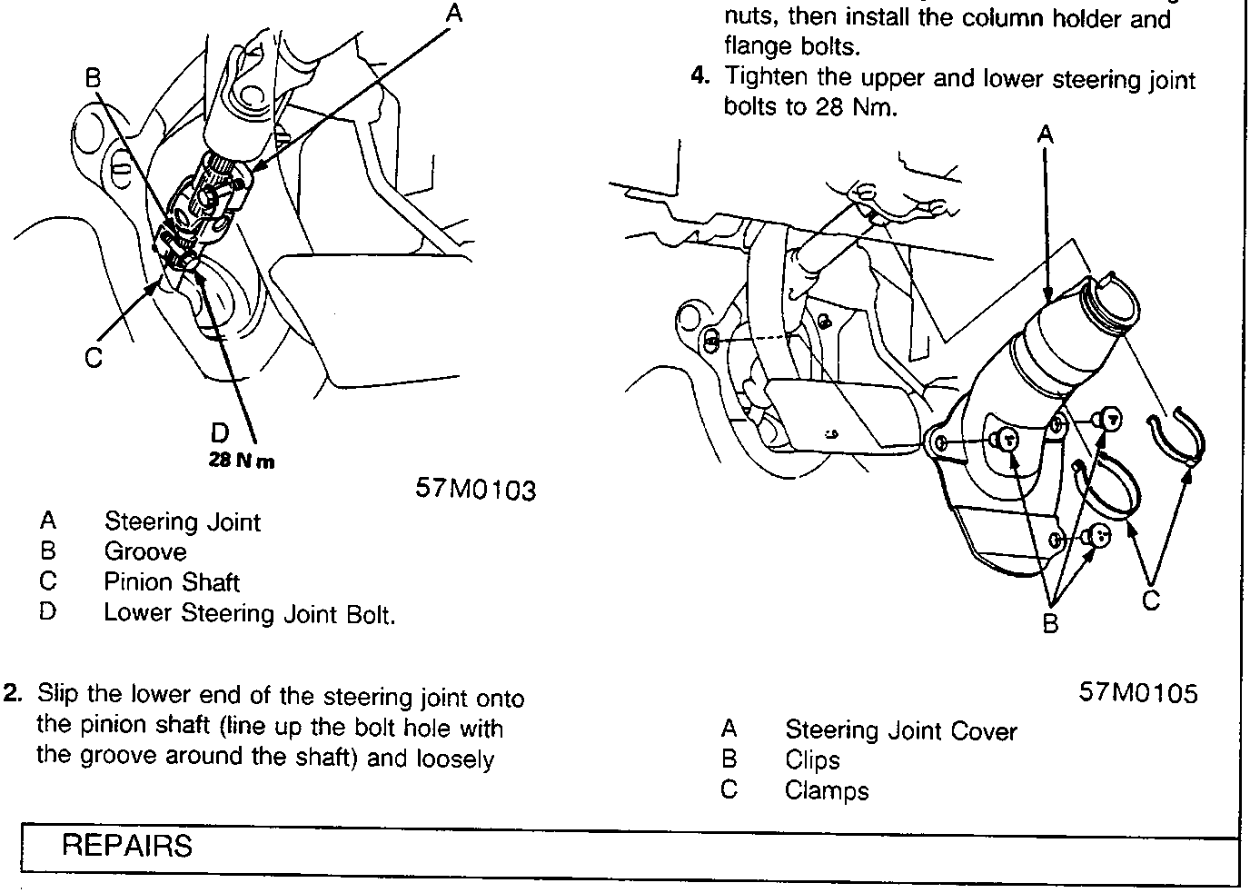
- Slip the lower end of the steering joint onto the pinion shaft (line up the bolt hole with the groove around the shaft) and loosely install the steering joint bolts.
A Steering Joint
B Groove
C Pinion Shaft
D Lower Steering Joint Bolt.
Note:
- Be sure that the lower steering joint bolt is securely in the groove in the pinion shaft.
- Before tightening the steering joint bolts pull on the steering joint to make sure that the steering joint is fully seated.
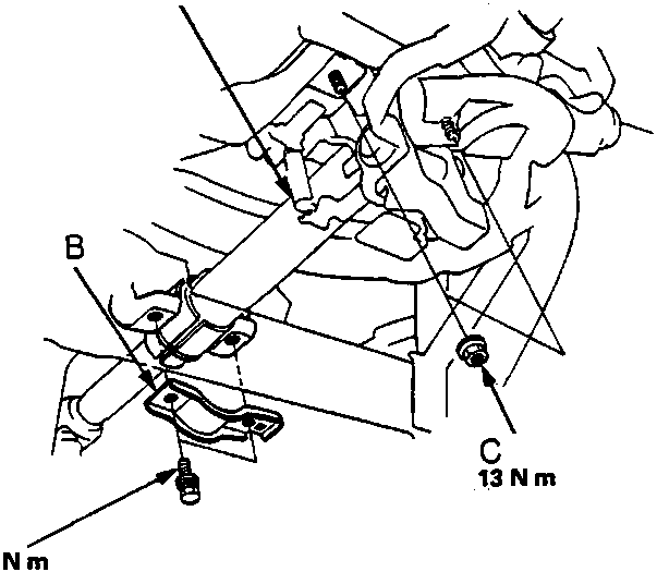
- Install the steering column with the flange nuts, then install the column holder and flange bolts.
- Tighten the upper and lower steering joint bolts to 28 Nm.
A Steering Column
B Column Holder
C Flange Nuts
D Flange Bolts
A Steering Joint Cover
B Clips
C Clamps
Parts & tools for this job For Rover 600
- TOOLTie rod end toolSearch: tie rod end puller
- TOOLBall joint separatorSearch: ball joint separator
- FLUIDPower steering fluidSearch: Rover power steering fluid
Links open Amazon search results in a new tab. As an Amazon Associate I earn from qualifying purchases.