
Steering Pump Construction
- Make
- Rover
- Model
- 600 Rover 600 Repair Manual - Volumes 1 and 2 - 2nd Edition
- Section
- Information › Steering Pump Construction
Steering Pump Construction
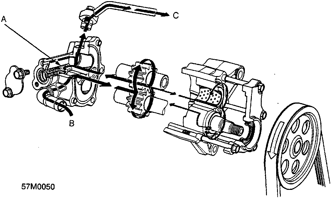
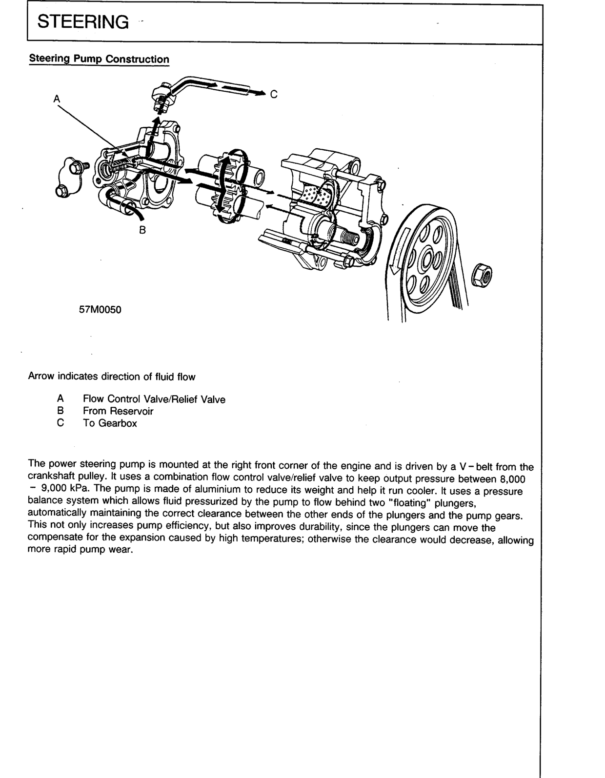
Arrow indicates direction of fluid flow
A Flow Control Valve/Relief Valve
B From Reservoir
C To Gearbox
The power steering pump is mounted at the right front corner of the engine and is driven by a V-belt from the crankshaft pulley. It uses a combination flow control valve/relief valve to keep output pressure between 8,000 – 9,000 kPa. The pump is made of aluminium to reduce its weight and help it run cooler. It uses a pressure balance system which allows fluid pressurized by the pump to flow behind two "floating" plungers, automatically maintaining the correct clearance between the other ends of the plungers and the pump gears. This not only increases pump efficiency, but also improves durability, since the plungers can move the compensate for the expansion caused by high temperatures; otherwise the clearance would decrease, allowing more rapid pump wear.
Original page
Parts & tools for this job For Rover 600
- TOOLTie rod end toolSearch: tie rod end puller
- TOOLBall joint separatorSearch: ball joint separator
- FLUIDPower steering fluidSearch: Rover power steering fluid
Links open Amazon search results in a new tab. As an Amazon Associate I earn from qualifying purchases.