
Description
- Make
- Rover
- Model
- 600 Rover 600 Repair Manual - Volumes 1 and 2 - 2nd Edition
- Section
- Information › Description
Note:
- All SRS electrical wiring harnesses are covered with YELLOW outer insulation.
- Replace the entire affected SRS harness assembly if it has an open circuit or damaged wiring.
- RHD type is symmetrical to LHD type.
CAUTION: Make sure all SRS earth locations are clean and earths are securely attached.
DESCRIPTION
The SRS is a safety device which, when used in conjunction with a seat belt, is designed to help protect the driver and front passenger in a frontal impact exceeding a certain set limit. The system consists of the SRS unit (including safing sensor and impact sensor), the cable reel and driver's airbag and front passenger's airbag.
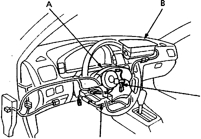
- Drivers airbag assembly
- Front passenger's airbag assembly
- SRS unit
- Cable reel
Operation
The main circuits in the SRS unit senses and judges the force of impact and, if necessary, ignites the inflator charges. If battery voltage is too or power is disconnected due to the impact, the back – up power circuit will keep voltage at a constant level.
For the SRS to operate:
- The impact sensor and the safing – sensor activate and send electric signals to the micro processor.
- The micro processor must compute the signals and must send to the airbag inflators.
- The inflators must ignite and deploy the airbags.
It takes about 0.1 seconds from the beginning of the airbag deployment until it is completely deflated.
Parts & tools for this job For Rover 600
- TOOLOBD2 scanner with SRSSearch: OBD2 scanner ABS SRS
- TOOLTrim removal tool kitSearch: trim removal tool kit
Links open Amazon search results in a new tab. As an Amazon Associate I earn from qualifying purchases.