
Circuit diagram (page 6 of 6)
- Make
- Rover
- Model
- 600 Rover 600 Repair Manual - Volumes 1 and 2 - 2nd Edition
- Section
- Information
Supplementary restraint system (SRS)Circuit diagram · page 6 of 6
The following components are located in the passenger compartment.
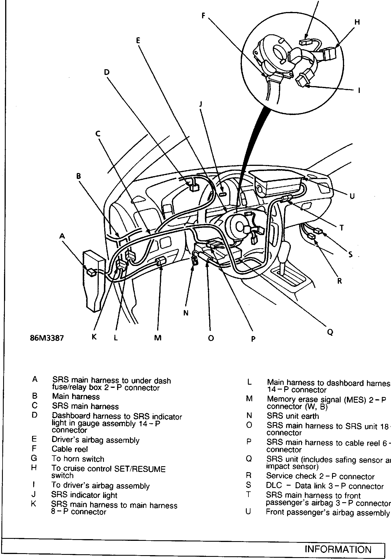
- A SRS main harness to under dash fuse/relay box 2 – P connector
- B Main harness
- C SRS main harness
- D Dashboard harness to SRS indicator light in gauge assembly 14 – P connector
- E Driver’s airbag assembly
- F Cable reel
- G To horn switch
- H To cruise control SET/RESUME switch
- I To driver’s airbag assembly
- J SRS indicator light
- K SRS main harness to main harness 8 – P connector
- L Main harness to dashboard harness 14 – P connector
- M Memory erase signal (MES) 2 – P connector (W, B)
- N SRS unit earth
- O SRS main harness to SRS unit 18 – P connector
- P SRS main harness to cable reel 6 – P connector
- Q SRS unit (includes safing sensor and impact sensor)
- R Service check 2 – P connector
- S DLC – Data link 3 – P connector
- T SRS main harness to front passenger’s airbag 3 – P connector
- U Front passenger’s airbag assembly
Parts & tools for this job For Rover 600
- TOOLDigital multimeterSearch: automotive digital multimeter
- PARTAssorted fuse kitSearch: car fuse assortment kit
- TOOLWire crimper and connector kitSearch: wire crimper connector kit
Links open Amazon search results in a new tab. As an Amazon Associate I earn from qualifying purchases.