
Passenger's Airbag
- Make
- Rover
- Model
- 600 Rover 600 Repair Manual - Volumes 1 and 2 - 2nd Edition
- Section
- Repairs › Passenger's Airbag
Supplementary restraint system (SRS)Passenger's Airbag
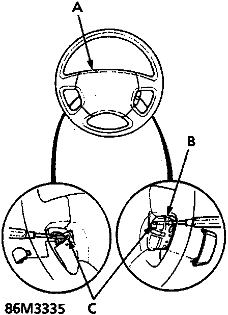
A Driver's airbag assembly
B Cruise control SET/RESUME switch
C TORX bolts
- Remove 2 covers from side of steering wheel hob.
- Remove the special bolts using a TORX T30 bit, then remove the airbag assembly.
Passenger's Airbag
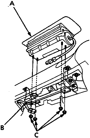
A Passenger's airbag module
B Module bracket
C Airbag mounting nuts
CAUTION: Both the airbag and the joint brackets are retained with self-locking flange nuts, the nuts for each application and the torque used are different.
- Remove 4 nuts securing the airbag, then lift the airbag out of the module bracket.
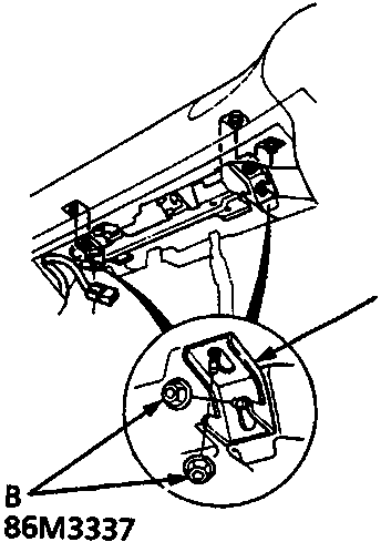
A Joint bracket
B Mounting nuts
9. Remove 4 nuts and the 2 joint brackets.
Parts & tools for this job For Rover 600
- TOOLOBD2 scanner with SRSSearch: OBD2 scanner ABS SRS
- TOOLTrim removal tool kitSearch: trim removal tool kit
Links open Amazon search results in a new tab. As an Amazon Associate I earn from qualifying purchases.