
Vehicle with driver's airbag
- Make
- Rover
- Model
- 600 Rover 600 Repair Manual - Volumes 1 and 2 - 2nd Edition
- Section
- Repairs › Vehicle with driver's airbag
Supplementary restraint system (SRS)Vehicle with driver's airbag · page 1 of 6
Vehicle with driver's airbag
WARNING: Store a removed airbag assembly with the pad surface up, if the airbag is improperly stored face down, accidental deployment could propel the unit with enough force to cause serious injury.
CAUTION:
- Before beginning work related to the SRS system, turn the ignition switch off, disconnect the negative and positive battery cables, and wait three minutes.
- Do not install used SRS parts from another car. When repairing an SRS, use only new parts.
- Do not disassemble the slip ring. It has no serviceable parts and has to be replaced as a whole.
- Replace the slip ring every 10 years.
- The slip ring is a special part of models equipped with SRS. When replacing, be sure to use only a genuine Rover spare part.
- Make sure the wheels are aligned straight ahead. Remove the left airbag assembly mounting special bolt first (the safety switch will automatically turn off).
- Remove the steering wheel, then remove the upper and lower steering column covers.
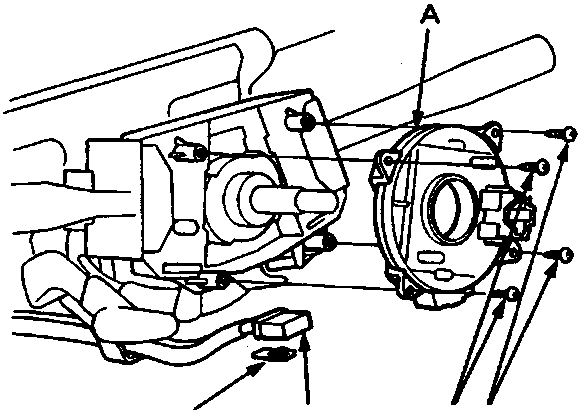
- A Slip ring
- B Mounting screw
- C SRS main harness 5 – P connector
- D Connector lock
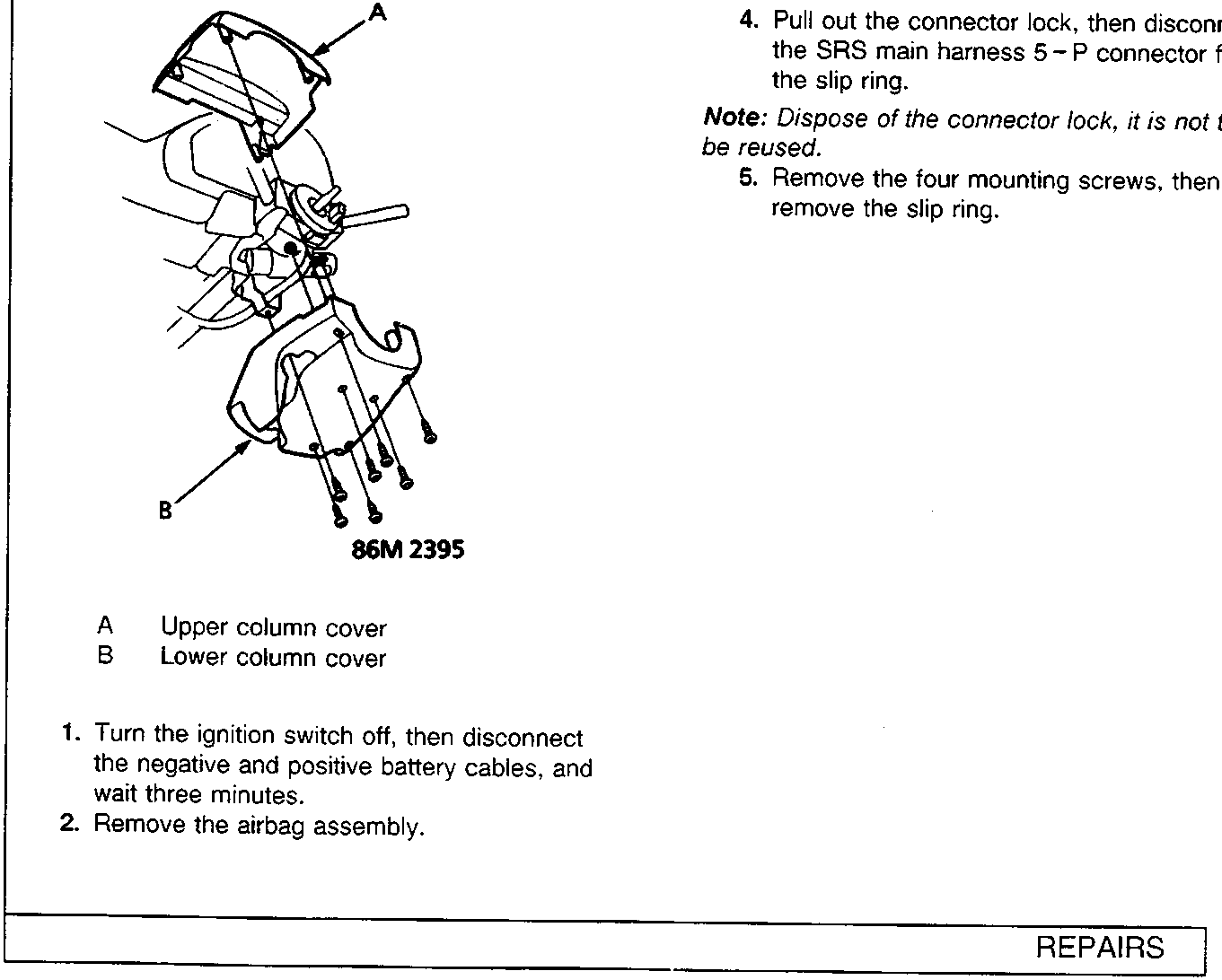
- A Upper column cover
- B Lower column cover
- Turn the ignition switch off, then disconnect the negative and positive battery cables, and wait three minutes.
- Remove the airbag assembly.
- Pull out the connector lock, then disconnect the SRS main harness 5 – P connector from the slip ring.
Note: Dispose of the connector lock, it is not to be reused.
- Remove the four mounting screws, then remove the slip ring.
Parts & tools for this job For Rover 600
- TOOLOBD2 scanner with SRSSearch: OBD2 scanner ABS SRS
- TOOLTrim removal tool kitSearch: trim removal tool kit
Links open Amazon search results in a new tab. As an Amazon Associate I earn from qualifying purchases.