
Vehicle with driver's airbag (page 6 of 6)
- Make
- Rover
- Model
- 600 Rover 600 Repair Manual - Volumes 1 and 2 - 2nd Edition
- Section
- Repairs
Supplementary restraint system (SRS)Vehicle with driver's airbag · page 6 of 6
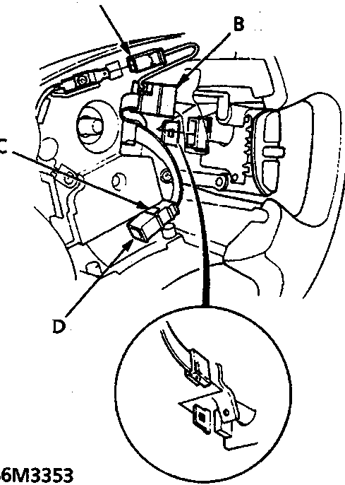
86M3353
- A Horn connector
- B Cruise control switch connector
- C Clip
- D Cable reel 3-P connector
- Install the steering wheel and attach the cable reel 3 - P connector to the clip.
- Connect the horn connector and the cruise control switches connectors.
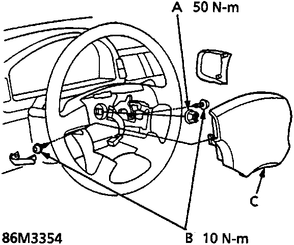
86M3354
- A Steering wheel nut
- B Torx bolts
- C Driver's airbag assembly
- Fit the steering wheel nut.
- Install the driver's airbag assembly.
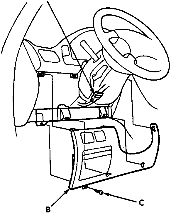
86M3355
- A Cable reel 6 - P connector
- B Dashboard lower cover
- C Screw
- Connect the cable reel 6 - P connector to the SRS main harness, then fit the dashboard lower cover.
- Remove and store the short connectors - RED, then reconnect the airbag connectors. Refit the glovebox.
- Reconnect the battery positive cable and then the negative cable.
Parts & tools for this job For Rover 600
- TOOLOBD2 scanner with SRSSearch: OBD2 scanner ABS SRS
- TOOLTrim removal tool kitSearch: trim removal tool kit
Links open Amazon search results in a new tab. As an Amazon Associate I earn from qualifying purchases.