
Exhaust manifold (page 2 of 4)
- Make
- Rover
- Model
- 600 620 Diesel Repair Manual Supplement
- Year
- 1995–1999
- Section
- Repairs
Manifold & exhaust systemsExhaust manifold · page 2 of 4
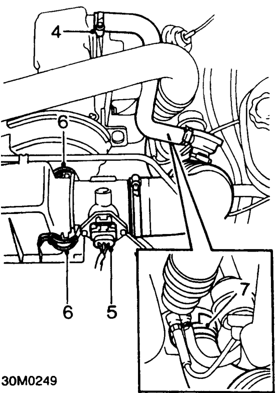
- Slacken clip and disconnect breather hose from camshaft cover.
- Disconnect multiplug from air flow meter
- Release 2 clips securing air flow meter housing to air filter.
- Slacken clip and disconnect air intake hose from turbocharger.
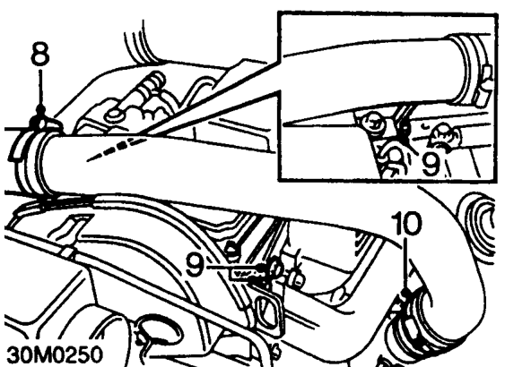
- Slacken clip and disconnect intercooler hose from turbocharger pipe.
- Remove 3 bolts securing turbocharger pipe to cylinder head, collect engine lifting bracket.
- Slacken clip and disconnect pipe from turbocharger.
- Remove turbocharger pipe.
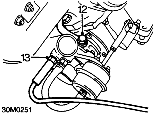
- Remove banjo bolt securing oil feed pipe to turbocharger, collect 2 sealing washers.
- Disconnect boost pressure sensing pipe from turbocharger.
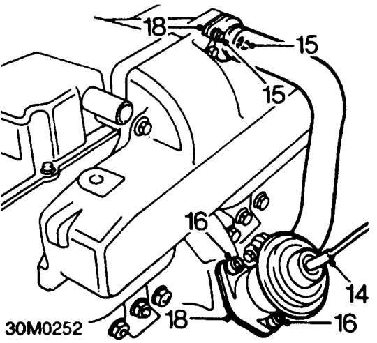
- Disconnect vacuum pipe from EGR valve.
- Remove 2 bolts securing recirculation pipe to inlet manifold.
- Remove 2 Allen screws securing EGR valve to exhaust manifold.
- Release and remove EGR valve.
- Remove and discard gasket.
- Raise front of vehicle.
WARNING: Support on safety stands.
Parts & tools for this job For 1995 Rover 600
- PARTExhaust gasketSearch: Rover 600 1995 exhaust gasket
- TOOLPenetrating oilSearch: penetrating oil
- TOOLOBD2 scannerSearch: OBD2 scanner
Links open Amazon search results in a new tab. As an Amazon Associate I earn from qualifying purchases.