
Refit
- Make
- Rover
- Model
- Coupé, Cabriolet & Tourer 200/400 Coupé, Cabriolet & Tourer Workshop Manual
- Section
- Repairs › Refit
Manual gearbox 1.4Refit
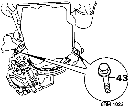
- Remove remaining 2 bolts securing gearbox to engine.
- Release gearbox from engine.
- Lower gearbox and, using assistance, manoeuvre gearbox down on to a trolley jack. Remove lifting hook and remove gearbox from under vehicle.
Refit
- Position gearbox under vehicle and connect lifting hook to gearbox.
- Raise gearbox and, using assistance manoeuvre gearbox into position on 2 engine dowels.
- Position A/C pipe bracket to gearbox. Clean and degrease threads on 2 upper bolts, apply sealant and fit securing gearbox to engine.
- Fit 2 lower bolts securing gearbox to engine.
- Tighten 4 gearbox to engine bolts to 85 Nm.
- Fit bracket to gearbox, fit 2 bolts and tighten to 100 Nm.
- Place L.H. mounting in position on body, raise engine until it is aligned.
- Fit 4 L.H. mounting to body bolts and tighten to 45 Nm.
- Fit 2 L.H. mounting to gearbox bolts and tighten to 60 Nm.
- Remove the jack and lifting equipment.
- Align steady bar and anti - beaming bracket to gearbox. Fit bolt securing steady bar and anti - beaming bracket to gearbox. Fit remaining bolt steady bar to gearbox and tighten both bolts to 100 Nm.
- Tighten bolt steady bar to body bracket to 85 Nm.
- Align A/C pipe to bracket, fit and tighten bolt.
- Fit flywheel rear cover plate and tighten 2 bolts to 8 Nm.
- Position clutch cable support and harness bracket to gearbox flange and fit and tighten 2 bolts to 38 Nm.
- Fit flywheel front cover plate and tighten 3 bolts to 8 Nm.
- Fit flywheel lower cover plate and tighten 3 bolts to 8 Nm.
- Connect both drive shafts to differential, see Differential oil seal – Repairs.
- Clean speedometer cable and its mating face, lubricate 'O' rings and connect cable to gearbox. Fit rubber securing pin.
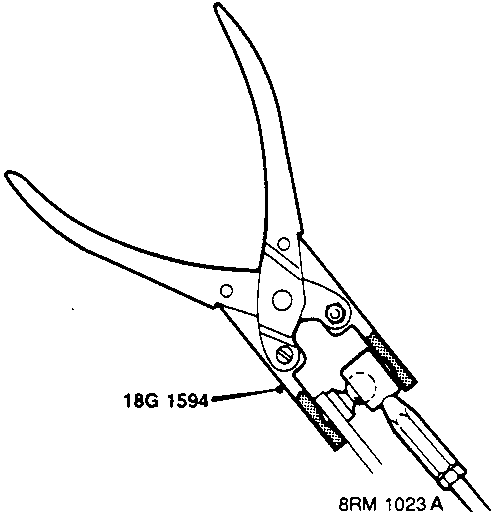
- Use tool 18G 1594, connect gear change ball joint to shaft and selector lever; ensure dust cover is positioned correctly.
- Align gear selector lever with linkage and, using tool 18G 1594, connect gear change ball joint; ensure dust cover is positioned correctly.
- Fit starter motor, see ELECTRICAL – Repairs.
- Connect 2 reverse lamp switch Lucars.
- Connect clutch cable to release lever, see CLUTCH – Repairs – Clutch Cable – 1.4.
- Fit underbelly panel, see BODY – Repairs.
- Fit road wheel and tighten nuts to 100 Nm.
- Remove stand(s) and lower vehicle.
- Remove gearbox filler/level plug and fill with correct quantity and grade of oil, see INFORMATION – CAPACITIES, FLUIDS AND LUBRICANTS.
- Fit the filler level plug and tighten to 25 Nm.
- Fit battery into tray, fit clamp and tighten bolt. Connect both battery leads.
Parts & tools for this job For Rover Coupé, Cabriolet & Tourer
- PARTClutch kitSearch: Rover Coupé, Cabriolet & Tourer clutch kit
- TOOLClutch alignment toolSearch: clutch alignment tool
- FLUIDGear oilSearch: Rover Coupé, Cabriolet & Tourer manual gearbox oil
Links open Amazon search results in a new tab. As an Amazon Associate I earn from qualifying purchases.