
Gearbox assembly
- Make
- Rover
- Model
- Coupé, Cabriolet & Tourer 200/400 Coupé, Cabriolet & Tourer Workshop Manual
- Section
- Repairs › Gearbox assembly
Manual gearbox 1.4Gearbox assembly · page 1 of 3
CAUTION: Pull joint to ensure circlip is fully engaged and retains shaft.
- Engage lower ball joint with hub.
- Fit lower ball joint nut and tighten to 60 Nm.
- Secure nut with a new split pin.
- Fit steering arm ball joint.
- Fit steering arm ball joint nut and tighten to 44 Nm.
- Secure nut with a new split pin.
- Align brake hose bracket to damper. Fit bolt bracket to damper and tighten to 25 Nm.
- Fit road wheel and tighten nuts to 100 Nm.
- Remove stand(s) and lower vehicle.
- Check and top up the gearbox oil, see MAINTENANCE.
GEARBOX ASSEMBLY
Service Repair No. 37.20.02
Remove
- Raise front of vehicle.
WARNING: Support on safety stands.
- Remove underbelly panel, see BODY – Repairs.
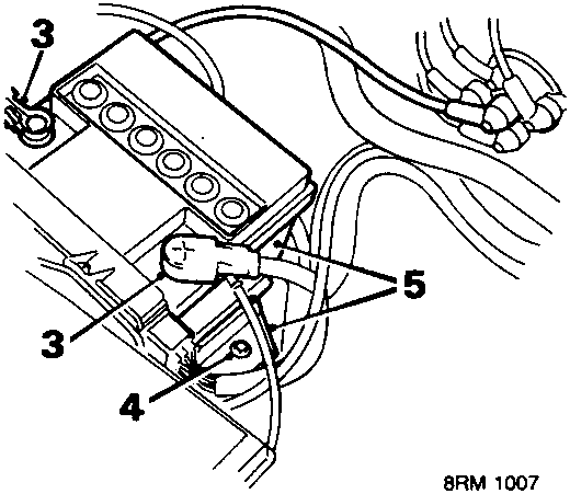
- Disconnect both battery leads.
- Remove clamp bolt.
- Remove battery clamp and lift out battery.
- Disconnect clutch cable from release lever, see CLUTCH – Repairs – Clutch Cable – 1.4.
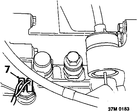
- Disconnect 2 reverse lamp switch Lucars.
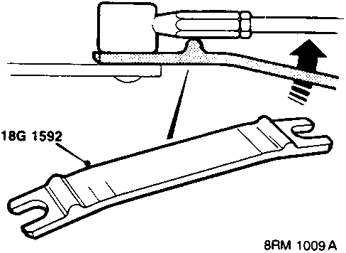
- Taking care not to damage dust cover, insert tool 18G 1592 between gear change linkage ball joint and gear selector lever.
- Use tool 18G 1592 to release gear change linkage ball joints from gear selector lever and shaft and lever selector.
- Move gear selector lever towards engine so that it clears subframe.
- Remove starter motor see ELECTRICAL – Repairs.
- Position a drain tin below gearbox.
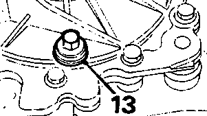
- Using hexagon socket, remove gearbox filler/level and drain plugs and drain the oil.
- Refit plugs and tighten to 25 Nm.
- Remove both front road wheels
- Release both drive shafts from differential and retain clear of gearbox, see Differential oil seal – Repairs.
Parts & tools for this job For Rover Coupé, Cabriolet & Tourer
- PARTClutch kitSearch: Rover Coupé, Cabriolet & Tourer clutch kit
- TOOLClutch alignment toolSearch: clutch alignment tool
- FLUIDGear oilSearch: Rover Coupé, Cabriolet & Tourer manual gearbox oil
Links open Amazon search results in a new tab. As an Amazon Associate I earn from qualifying purchases.