
Connector a
- Make
- Alfa Romeo
- Model
- 145/146 Electrical System Diagnosis Manual, Volume 3
- Year
- 1994–2001
- Section
- Automatic Air Conditioner › Connector a
145 electrical system diagnosisConnector a
PIN OUT Control unit
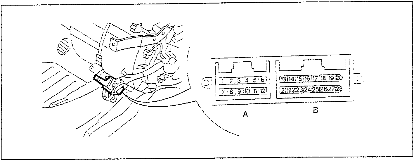
CONNECTOR A
| PIN | FUNCTION |
|---|---|
| 1 | "Fast defrosting" function |
| 2 | Compressor engagement |
| 3 | Earth |
| 4 | Fan control potentiometer |
| 5 | Required temperature adjustment potentiometer |
| 6 | Treated air temp. sensor |
| 7 | Recirculation engagement |
| 8 | Diagnosis line K |
| 9 | Diagnosis line L |
| 10 | Supply for potentiometers - 5V |
| 11 | Direct supply from battery |
| 12 | Earth for sensors |
CONNECTOR B
| PIN | FUNCTION |
|---|---|
| 13 | Earth |
| 14 | Passenger compartment temperature sensor |
| 15 | Outside temperature sensor |
| 16 | N.C. |
| 17 | Mixing actuator feed-back |
| 18 | Antifrost sensor |
| 19 | N.C. |
| 20 | Fan control |
| 21 | Earth for fan |
| 22 | Mixer control - 5V |
| 23 | Mixer control - 5V |
| 24 | Compressor control |
| 25 | Key supply |
| 26 | Recirculation engagement control- 5V |
| 27 | Recirculation shut off control - 5V |
| 28 | N.C. |
Parts & tools for this job For 1994 Alfa Romeo 145/146
- TOOLDigital multimeterSearch: automotive digital multimeter
- PARTAssorted fuse kitSearch: car fuse assortment kit
- TOOLWire crimper and connector kitSearch: wire crimper connector kit
Links open Amazon search results in a new tab. As an Amazon Associate I earn from qualifying purchases.