
Exhaust system description
- Make
- Alfa Romeo
- Model
- 145/146 Engines, 146 Bodywork and Engine Overhaul Manual
- Year
- 1994–2001
- Section
- Exhaust system › Exhaust system description
EXHAUST SYSTEM DESCRIPTION
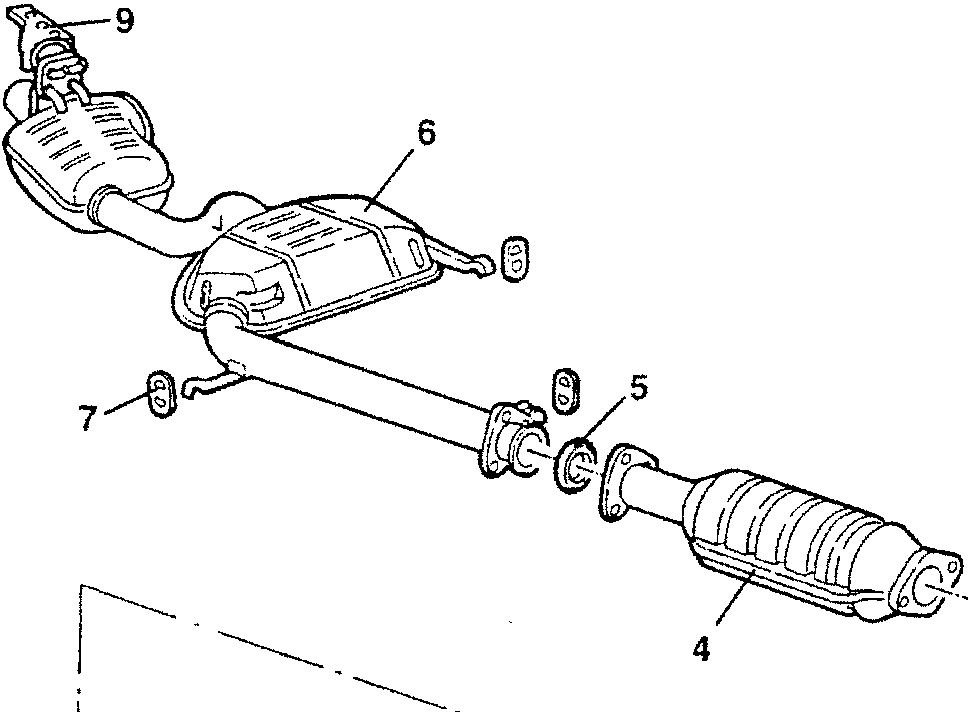
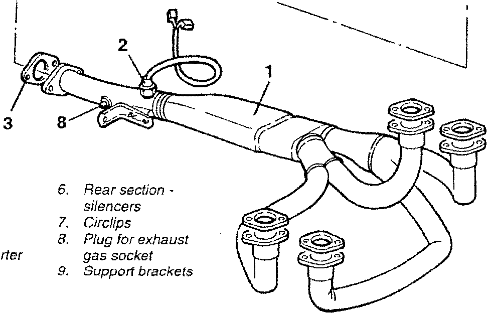
- Front section - manifolds
- Lambda probe
- Seals
- Catalytic converter
- Seal ring
- Rear section - silencers
- Circlips
- Plug for exhaust gas socket
- Support brackets
The exhaust gases flow from the cylinder heads into the manifolds of the front section of the exhaust pipe. On the front section of the exhaust pipe the lambda sensor is fitted which informs the control unit of the amount of oxygen contained in the exhaust gas thus enabling the injection times to be adjusted to keep the stoichiometric ratio (air-fuel) at an optimum level. On the front section of the exhaust pipe, there is also the plug for the exhaust gas socket upstream of the catalytic converter. From the front section, the exhaust gases reach the catalytic converter where most of the pollutants are transformed. From the catalytic converter the exhaust gases reach the two silencers of the rear section of the exhaust pipe.
The various sections of the exhaust pipe are connected by flanges with seals and support to the body is made by brackets and circlips.
The radiation of heat towards the body, which is very high due to the catalytic converter, is limited by a set of heat shields.
During engine operation all the exhaust pipes and in particular the catalytic converter heat up considerably.
Before attempting any work, the system should be left to cool with the engine switched off.
NEVER TOUCH THE CATALYTIC CONVERTER WITHOUT ADEQUATE PROTECTION SUCH AS GLOVES, ETC.
DO NOT ALLOW EASILY INFLAMMABLE MATERIAL TO COME INTO CONTACT WITH THE CATALYTIC CONVERTER.
Parts & tools for this job For 1994 Alfa Romeo 145/146
- PARTExhaust gasketSearch: Alfa Romeo 145/146 1994 exhaust gasket
- TOOLPenetrating oilSearch: penetrating oil
- TOOLOBD2 scannerSearch: OBD2 scanner
Links open Amazon search results in a new tab. As an Amazon Associate I earn from qualifying purchases.