
Operation
- Make
- Alfa Romeo
- Model
- 145/146 Engines, 146 Bodywork and Engine Overhaul Manual
- Year
- 1994–2001
- Section
- Fuel supply system › Operation
OPERATION
The injector works in three steps:
- "rest position"
The coil (4) is de-energised and the shutter (6) is in the closed position and does not allow the delivery of fuel into the cylinder Fc > Fa (Fc: due to the line pressure which acts directly on the control area 7 of the rod 1; Fa: due to the line pressure which acts in the supply volume 8).
- "start of injection"
The coil (4) is energised and causes the shutter (6) to rise.
The fuel of the control volume (9) flows towards the return manifold (10) causing a pressure drop on the control area (7).
Simultaneously, the line pressure through the supply duct (12) exerts a force Fa > Fc in the supply volume (8) causing the pin (2) to rise, thereby sending fuel into the cylinders.
- "end of injection"
The coil (4) is de-energised and makes the shutter (6) return to the closed position which again creates a balance of force which returns the pin (2) to the closed position, resulting in the end of injection.
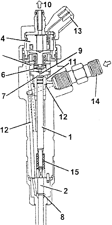
- Pressure rod
- Pin
- Nozzle
- Coil
- Drive valve
- Ball shutter
- Control area
- Supply volume
- Control volume
- Fuel return - low pressure
- Control duct
- Supply duct
- Electrical connection
- Fuel inlet - high pressure coupling
- Spring
REMOVAL/REFITTING
- Make sure that the ignition key is at "STOP", then disconnect the battery terminal (-).
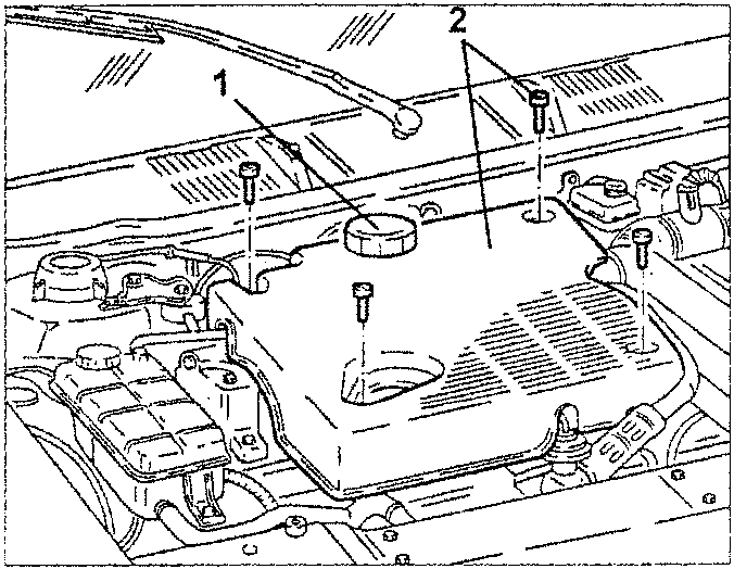
- Remove the engine oil filler cap.
- Slacken the fastening screws and remove the engine cover.
- Refit the engine oil filler cap.
Parts & tools for this job For 1994 Alfa Romeo 145/146
- PARTEngine gasket setSearch: Alfa Romeo 145/146 1994 engine gasket set
- TOOLTorque wrenchSearch: 3/8 inch torque wrench
- TOOLFeeler gauge setSearch: feeler gauge set
Links open Amazon search results in a new tab. As an Amazon Associate I earn from qualifying purchases.