
Flexible recks drawing the sunroof
- Make
- Alfa Romeo
- Model
- 145/146 Factory Service Manual
- Year
- 1994–1999
- Section
- Internal trim › Flexible recks drawing the sunroof
BodyworkFlexible recks drawing the sunroof · page 1 of 2
FLEXIBLE RECKS DRAWING THE SUNROOF
REMOVAL
- Remove the sunroof motor (see specific paragraph).
- Remove the sunroof (see specific paragraph).
- Remove the sliding blind (see specific paragraph).
- Remove the stroke limit microswitch (see specific paragraph).
- Withdraw the left rack from the guide sheath.
- Slacken the two screws fastening the rack stop plate.
- Remove the rack stop plate from the right guide.
- Withdraw the right rack from the guide sheath.
POSITIONING THE SUNROOF CONTROL SYSTEM
- Move the front runner to the foremost position.
- Position the rear runner so that the pin of the safety microswitch (left guide) or the hole (right guide) coincide respectively with the switch or reference pin; this way the two guides will correspond perfectly.
GUIDES
REMOVAL/REFITTING
- Disconnect the battery negative pole (-).
- Remove the sunroof glass (see specific paragraph).
- Remove the sliding blind (see specific paragraph).
- Slacken the two screws fastening the microswitch to the guide and remove it releasing the left rack.
- Slacken the two screws fastening the cable clamp plate.
- Slacken the four screws fastening the guide to the frame..
- Remove the guides releasing them from the retainer clips of the centering device fastened behind the frame.
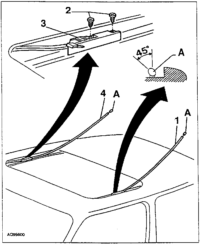
NOTA: When the end of the rack is level with the drawing gear housing, check that it centres the second section of the guide. Once it is completely inserted, check that the elliptical head (A) is positioned in its housing sloping 45° towards the inside of the car.
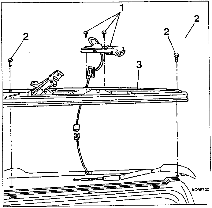
- Control lever
- Guide screws
- Centering device
- Position the rack stop plate and fasten it with the two screws.
- Repeat the operation for the left rack, then complete refitting reversing the sequence described for removal.
- Position the control system (see specific paragraph).
Parts & tools for this job For 1994 Alfa Romeo 145/146
- TOOLTrim removal tool kitSearch: trim removal tool kit
- PARTTouch-up paintSearch: Alfa Romeo touch up paint
- PARTPanel clip assortmentSearch: Alfa Romeo panel clips assortment
Links open Amazon search results in a new tab. As an Amazon Associate I earn from qualifying purchases.