
Brake servo/brake pump assembly - r r
- Make
- Alfa Romeo
- Model
- 147 Factory Service Manual
- Year
- 2000–2004
- Section
- Hydraulic braking system › Brake servo/brake pump assembly - r r
Brake servo/brake pump assembly - r r
Removing
Position the vehicle on the ramp.
Proceed with removal - 5530B10 battery - r+r.
Proceed with removal - 5530B52 Battery DRIP TRAY/SUPPORT - R.R..
Proceed with removal - 3340A12 A'B.S. system. - electronic and hydraulic CONTROL UNIT R.R..
Proceed with removal - 3340A13 abs central mount - r r.
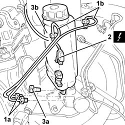
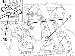
1. Undo the connectors (1a) and remove the rigid pipe from the master cylinder to the A.B.S. hydraulic control unit (1b).
2. Disconnect the electrical connection from the low brake-clutch fluid warning light switch.
| Name | Connector | |
|---|---|---|
| 2 | Brake fluid level sensor (switch) | K25 |
3. Undo the bolt (3a) and move the brake-clutch fluid reservoir (3b) over to the side.
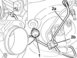
1. Disconnect the single-acting valve from the brake servo.
2. Release the rigid pipe from the A.B.S. hydraulic control unit to the right front brake (2a) from the retaining band (2b).
Working in the interior compartment, prise off the buttons and remove the trim.
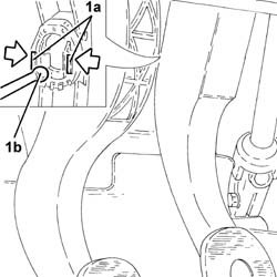
1. Release the retaining clips (1a) and disengage the brake pump (1b) from the brake pedal.
Take care not to damage the retaining clips.
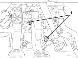
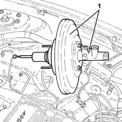
1. Undo the nuts securing the brake servo/brake pump assembly to the pedal assembly.
1. Working from the engine compartment, remove the brake servo/brake pump assembly.
Refitting
Working from the engine compartment, refit the brake servo/brake pump assembly in its seating.
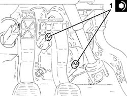
1. Working from the engine compartment, tighten the nuts securing the brake servo/brake pump assembly to the pedal assembly mounting.
| Fastening | Component | Ø | Value (daNm) | |
|---|---|---|---|---|
| 1 | Nut | BRAKE SERVO | M8 | 2.2 |
Connect the brake pump to the brake pedal.
Refit the trim in its seating and fix it with the buttons.
Secure the rigid pipe from the A.B.S. hydraulic control unit to the right front brake to the retaining band.
Connect the one-way valve to the brake servo.
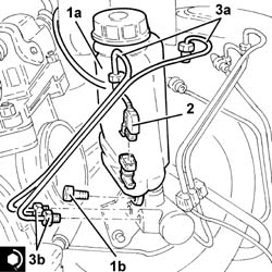
1. Refit the brake-clutch fluid reservoir (1a) in its seating and secure it with its bolt (1b).
2. Connect the electrical connection to the low brake-clutch fluid warning light switch.
3. Place the rigid pipes from the master cylinder to the A.B.S. hydraulic control unit (3a) in their seats and tighten the connectors (3b), master cylinder side, to the specified torque.
| Fastening | Component | Ø | Value (daNm) | |
|---|---|---|---|---|
| 3b | Connector | PIPE FROM PUMP TO HYDRAULIC CONTROL UNIT | M12 | (Master cylinder side) 1.3 ÷ 1.5 |
Proceed with refitting - 3340A13 abs central mount - r r.
Proceed with refitting - 3340A12 A'B.S. system. - electronic and hydraulic CONTROL UNIT R.R..
Proceed with refitting - 5530B52 Battery DRIP TRAY/SUPPORT - R.R..
Proceed with refitting - 5530B10 battery - r+r.
Bleed the air from the hydraulic braking system - 3330A14 HYDRAULIC BRAKING SYSTEM - Bleed air.
Remove the car from the ramps.
Removing
Position the vehicle on the ramp.
Proceed with removal - 5530B10 battery - r+r.
Proceed with removal - 5530B52 Battery DRIP TRAY/SUPPORT - R.R..
Proceed with removal - 3340A12 A'B.S. system. - electronic and hydraulic CONTROL UNIT R.R..
Proceed with removal - 3340A13 abs central mount - r r.
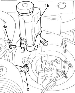
1. Undo the bolt (1a) and remove the brake-clutch fluid reservoir (1b).
2. Disconnect the single-acting valve from the brake servo.
1. Release the retaining clips (1a) and disengage the brake pump (1b) from the brake pedal.
Take care not to damage the retaining clips.
2. Undo the nuts securing the brake servo/brake pump assembly to the pedal assembly.
Proceed with removal - 4450B10 Front WHEEL (one) - R.R. (Left side).
Proceed with removal - 7055B64 Engine compartment DUST shield in front wheel arch (one), left or right - R.R. (Left side).
Proceed with removal - 7055B54 under-engine guard - r r.
Position a hydraulic jack under the gearbox.
1. Undo the bolts fixing the power unit gearbox side rigid support to the flexible mounting.
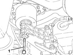
Lower the power unit, as necessary, using the hydraulic jack.
Working under the vehicle, withdraw the brake servo/brake pump assembly from its seating.
Tighten the bolt fixing the power unit gearbox side rigid support to the flexible mounting.
Remove the hydraulic jack from under the gearbox.
1. Working from the engine compartment, remove the brake servo/brake pump assembly.
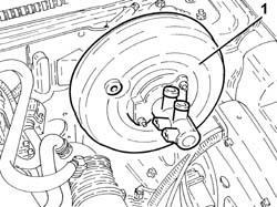
Refitting
Working from the engine compartment, temporarily refit the brake servo/brake pump assembly.
Position a hydraulic jack under the gearbox
Undo the bolts fixing the power unit gearbox side rigid support to the flexible mounting.
Working under the vehicle, refit the brake servo/brake pump assembly in its seating.
1. Undo the bolt fixing the gearbox side rigid power unit support to the flexbile block to the specified torque.
| Fastening | Component | Ø | Value (daNm) | |
|---|---|---|---|---|
| 1 | Bolt | POWER UNIT GEAR BOX END RIGID MOUNT | M12 | (Flexible mounting side) 8.8 |
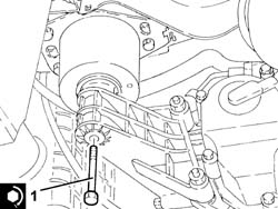
Remove the hydraulic jack from under the gearbox.
Proceed with refitting - 7055B54 under-engine guard - r r.
Proceed with the refitting - 7055B64 Engine compartment DUST shield in front wheel arch (one), left or right - R.R. (Left side).
Proceed with the refitting - 4450B10 Front WHEEL (one) - R.R. (Left side).
1. Working from the engine compartment, tighten the nuts securing the brake servo/brake pump assembly to the pedal assembly mounting.
| Fastening | Component | Ø | Value (daNm) | |
|---|---|---|---|---|
| 1 | Nut | BRAKE SERVO | M8 | 2.2 |
2. Connect the brake pump to the brake pedal.
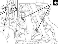
Connect the one-way valve to the brake servo.
Place the brake-clutch fluid reservoir back in its housing and secure it using the bolt.
Proceed with refitting - 3340A13 abs central mount - r r.
Proceed with refitting - 3340A12 A'B.S. system. - electronic and hydraulic CONTROL UNIT R.R..
Proceed with refitting - 5530B52 Battery DRIP TRAY/SUPPORT - R.R..
Proceed with refitting - 5530B10 battery - r+r.
Bleed the air from the hydraulic braking system - 3330A14 HYDRAULIC BRAKING SYSTEM - Bleed air.
Remove the car from the ramps.
Removing
Position the vehicle on the ramp.
Proceed with removal - 5530B10 battery - r+r.
Proceed with removal - 5530B52 Battery DRIP TRAY/SUPPORT - R.R..
Proceed with removal - 4450B02 left front wheel r r.
Proceed with removal - 3330C30 brake fluid reservoir - r + r and wash inside.
Proceed with removal - 3340A12 A'B.S. system. - electronic and hydraulic CONTROL UNIT R.R..
Proceed with removal - 3340A13 abs central mount - r r.
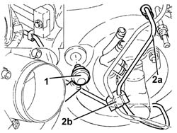
1. Disconnect the single-acting valve from the brake servo.
2. Release the rigid pipe from the A.B.S. hydraulic control unit to the right front brake (2a) from the retaining band (2b).
Working in the interior compartment, prise off the buttons and remove the trim.
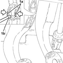
1. Release the retaining clips (1a) and disengage the brake pump (1b) from the brake pedal.
Take care not to damage the retaining clips.
1. Undo the nuts securing the brake servo/brake pump assembly to the pedal assembly.
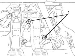
1. Working from the engine compartment, remove the brake servo/brake pump assembly.
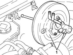
Refitting
Working from the engine compartment, refit the brake servo/brake pump assembly in its seating.
1. Working from the engine compartment, tighten the nuts securing the brake servo/brake pump assembly to the pedal assembly mounting.
| Fastening | Component | Ø | Value (daNm) | |
|---|---|---|---|---|
| 1 | Nut | BRAKE SERVO | M8 | 1.8 ÷ 2.6 |
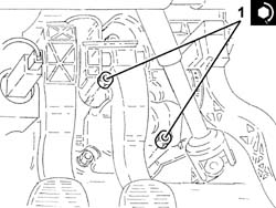
Connect the brake pump to the brake pedal.
Refit the trim in its seating and fix it with the buttons.
Secure the rigid pipe from the A.B.S. hydraulic control unit to the right front brake to the retaining band.
Connect the one-way valve to the brake servo.
Proceed with refitting - 3340A13 abs central mount - r r.
Proceed with refitting - 3340A12 A'B.S. system. - electronic and hydraulic CONTROL UNIT R.R..
Proceed with refitting - 3330C30 brake fluid reservoir - r + r and wash inside.
Proceed with refitting - 5530B52 Battery DRIP TRAY/SUPPORT - R.R..
Proceed with refitting - 5530B10 battery - r+r.
Top up the brake/clutch fluid level - 0010T64 brake and or clutch fluid check level and top up as necessary.
Bleed the air from the hydraulic braking system - 0010T65 hydraulic brake system bleed air.
Proceed with refitting - 4450B02 left front wheel r r.
Remove the car from the ramps.
Removing
Proceed with removal - 5530B10 battery - r+r.
When removing the battery, make sure also to disconnect the starter motor supply lead, shown in the figure, from the maxi fuse box.
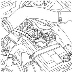
Proceed with removal - 3330C30 brake fluid reservoir - r + r and wash inside.
Proceed with draining the braking system using the bleed valve on the brake caliper rather than drawing it off from the reservoir using a suitable syringe.
1. Disconnect the electrical connection from the A.B.S. hydraulic and electronic control unit.
| Name | Connector | |
|---|---|---|
| 1 | ABS control unit | M50 |
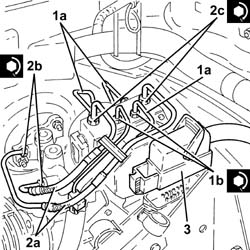
2. Undo the connectors (2a) and (2b) and remove the rigid pipes from the master cylinder to the ABS hydraulic control unit (2c).
3. Undo the connectors (3a) and disconnect the rigid pipes from the hydraulic control unit to the brake calipers (3b), hydraulic unit side.
4. Release the ABS pipes from the attachments.
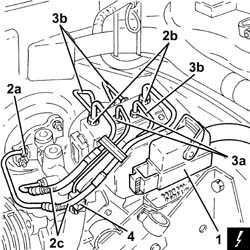
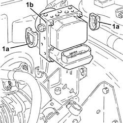
1. Remove the stops (1a) and remove the hydraulic and electronic unit of the ABS system (1b).
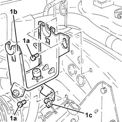
1. Undo the bolts (1a) and remove the support for the A.B.S. control unit (1b) after having released the clutch system pipe from the band (1c).
Working in the interior compartment, prise off the buttons and remove the trim.
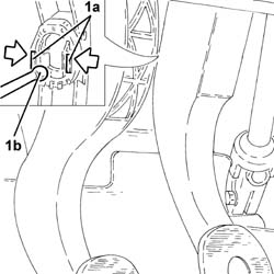
1. Release the retaining clips (1a) and disengage the brake pump (1b) from the brake pedal.
Take care not to damage the retaining clips.
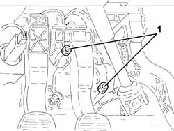
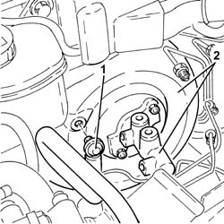
1. Undo the nuts securing the brake servo/brake pump assembly to the pedal assembly.
1. Disconnect the vacuum pipe, complete with single-acting valve, from the brake servo.
2. Release and remove the brake servo/brake pump assembly.
Refitting
Working in the engine compartment, refit the brake servo/brake pump assembly in its seating.
Connect the vacuum pipe, complete with single-acting valve, to the brake servo.
1. Working from the passenger compartment, tighten the nuts securing the brake servo/brake pump assembly to the pedal assembly mounting.
| Fastening | Component | Ø | Value (daNm) | |
|---|---|---|---|---|
| 1 | Nut | BRAKE SERVO | M8 | 2.1 ÷ 2.9 |
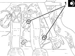
Connect the brake pump to the brake pedal.
Refit the trim in its seating and fix it with the buttons.
Secure the clutch system pipe to the band, then place the support for the A.B.S. control unit back in its housing and secure it using the bolts.
Place the ABS hydraulic and electronic unit back in its housing and secure it with its attachments.
Secure the A.B.S. pipes to the fastenings.
1. Connect the rigid pipes from the hydraulic unit to the brake calipers (1a), hydraulic unit side, and tighten the connectors (1b) to the specified torque.
| Fastening | Component | Ø | Value (daNm) | |
|---|---|---|---|---|
| 1b | Connector | RIGID CENTRE BRAKE PIPES../ | M10/M12 | (A.B.S.) control unit side 1.3 ÷ 1.5 |
2. Place in their seatings the rigid pipes from master cylinder to ABS hydraulic unit (2a) and tighten the connectors (2b) and (2c) to the recommended torque.
| Fastening | Component | Ø | Value (daNm) | |
|---|---|---|---|---|
| 2b | Connector | PIPE FROM PUMP TO HYDRAULIC CONTROL UNIT | M12 | (Master cylinder side) 1.3 ÷ 1.5 |
| Fastening | Component | Ø | Value (daNm) | |
|---|---|---|---|---|
| 2c | Connector | PIPE FROM PUMP TO HYDRAULIC CONTROL UNIT | M12 | (A.B.S.) control unit side 1.3 ÷ 1.5 |
3. Connect the electrical connection to the A.B.S. hydraulic and electronic control unit.
Proceed with refitting - 3330C30 brake fluid reservoir - r + r and wash inside.
Proceed with refitting - 5530B10 battery - r+r.
Bleed the air from the hydraulic braking system - 0010T65 hydraulic brake system bleed air.
Parts & tools for this job For 2000 Alfa Romeo 147
- PARTBrake padsSearch: Alfa Romeo 147 2000 brake pads
- TOOLBrake bleeder kitSearch: one man brake bleeder kit
- FLUIDBrake fluidSearch: brake fluid
Links open Amazon search results in a new tab. As an Amazon Associate I earn from qualifying purchases.