
E4090 Navigator
- Make
- Alfa Romeo
- Model
- 147 Factory Service Manual
- Year
- 2000–2002
- Section
- Instruments › E4090 Navigator
E4090 Navigator
Description
The navigation system informs you of the vehicle's position on the map (in relation to both urban and non-urban/motorway road networks), by showing it on the display. In this way, the driver is taken to the desired destination, guided step-by-step by voice messages and visual information. The system also provides additional information for reaching services of general interest, such as hotels, car parks, restaurants, pharmacies, service stations, hospitals, ALFA ROMEO garages, railway stations, airports, etc.
If present, the navigator is included in the integrated radio-telephone-navigator.
The navigation system uses the GPS (Global Positioning System) satellite location technology; it has the following functions:
- vehicle location
- calculation of the route
- identification of 'route guidance' manoeuvres
- management of the map data base (on CD-ROM)
- map display (only in the pictogram 'high' version)
- emission of corresponding voice messages
The navigation CD-ROM reader is located in the unit itself.
the navigation system operates only with the CD-ROM inserted in the specific drive; however it is possible to listen to a music CD during navigation. In this case, the navigation function requires the map CD to be inserted during execution of the route calculation procedures.
The GPS system consists of an aerial which allows the GPS satellite location of the vehicle: the aerial is connected to the relevant receiver, located in the integrated unit, via a specific shielded cable. The fishpole antenna is mounted at the rear of the roof: it has three functions (radio/GSM/GPS), as it also incorporates the GSM aerial and radio aerial.
The vehicle position is identified by the analysis of the GPS data and the speedometer and reverse gear signals coming from the car.
This position is shown on the display together with the topographical characteristics of the area memorised on the CD with the map (only in the 'high' version with pictograms).
In addition the Navigator generates a 'speech synthesis' which, viat the audio circuit, allows the driver to hear the driving instructions.
The integrated radio-telephone-navigator unit is a node on the CAN network, through which it exchanges information with the Body Computer and the other electronic units (for example the navigation system acquires the odometer, reverse gear engaged, etc. information)
The navigation commands displayed on the radio's display are repeated on the instrument panel ('HIGH' version).
By means of an appropriate menu activated by the control buttons located on the panel beside the steering wheel, the entire system can be configured and in particular the units of measurement and the display language.
For more details Characteristic of working principle 5570 Accessories .
Description of operation
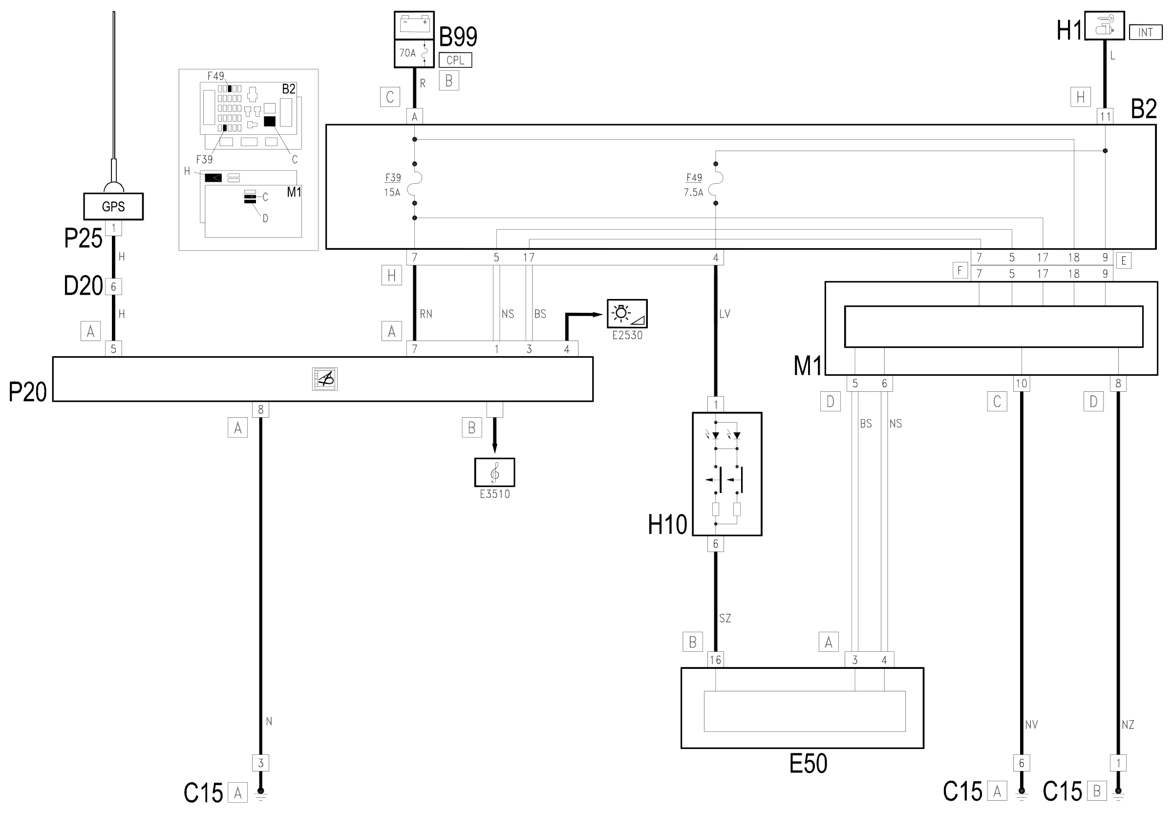
The integrated radio-telephone-navigator P20 is supplied directly (7 of connector A) from the battery via the line of the fuse F39 of the unit under the dashboard B2 and maxifuse CPL of B99.
Pin 4 of connector A receives the supply for side lights on Wiring diagram E2530 INSTRUMENT LIGHTING .
Pins 1 and 3 of connector A receive the CAN line with which the radio P20 is connected to the Body Computer M1 and the other nodes of the system.
Pin 8 of connector A is earthed.
The aerial P25 is supplied from pin 5 of connector A. The aerial containing the GPS reception device is connected to the navigator module by means of the specific coaxial cable.
Connector B sends out cables carrying signals to the speakers through which the voice messages are sent:
The 'MODE' buttons of the H10 controls unit are supplied by the line (INT) protected by the fuse F39 of control unit B2, and send the command to the instrument panel E50, pin 16 of connector B.
The instrument panel E50 is in turn connected via the CAN network to the Body Computer M1 and the integrated radio-telephone-navigator P20.
Wiring diagram
Components
| Code | Component | See |
|---|---|---|
| B02 | Junction unit under dashboard | description 5505A |
| B99 | Maxifuse box on battery | description 5530B |
| C15 | Facia earth, driver's side | |
| D20 | /Rear dashboard coupling | |
| H01 | Ignition switch | description 5520A |
| M01 | Body computer | description 5505A |
| P20 | Car radio | |
| P25 | Aerial amplifier / feeder |
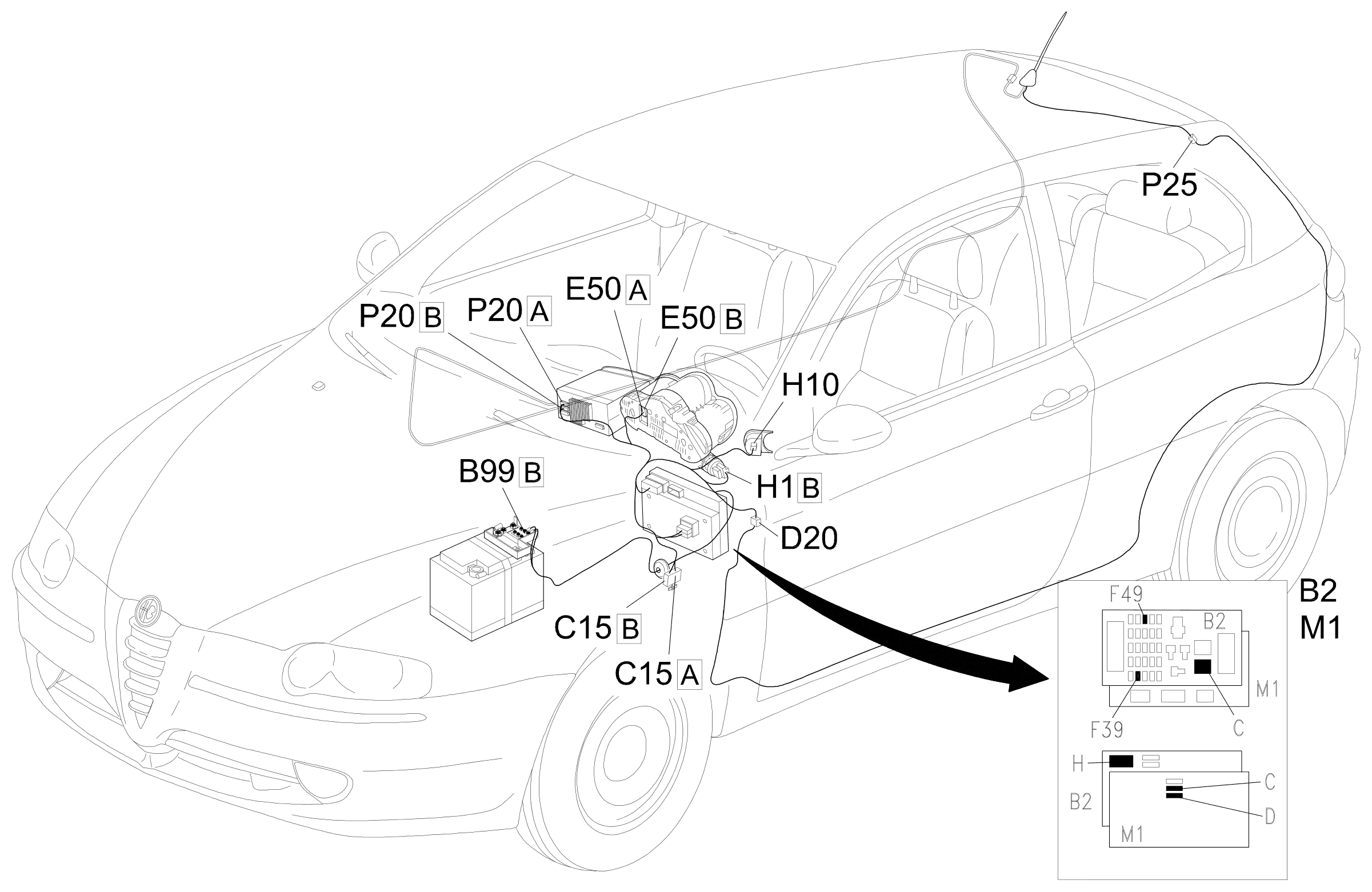
Component location
Parts & tools for this job For 2000 Alfa Romeo 147
- TOOLDigital multimeterSearch: automotive digital multimeter
- PARTAssorted fuse kitSearch: car fuse assortment kit
- TOOLWire crimper and connector kitSearch: wire crimper connector kit
Links open Amazon search results in a new tab. As an Amazon Associate I earn from qualifying purchases.