
Subframes: Specifications
- Make
- Aston Martin
- Model
- DB9 Factory Workshop Manual
- Year
- Issue 2, 2005
- Section
- Subframes › Specifications
02 Frame and mountingSpecifications
Specifications
| Torque Figures | ||
|---|---|---|
| Description | Nm. | lb. / ft. |
| Subframe to Front Structure | 105-125 | 77.5-92.5 |
| Subframe to Body | 105-125 | 77.5-92.5 |
| Engine Mounts | 47 | 35 |
| Steering Rack | 115 | 85 |
| Torque tube (rear) | 43-57 | 32-42.5 |
| Drive Plate (auto only) | 72 | 53.5 |
| Spring and Damper top mounting (rear) | 85 | 63 |
| Rear subframe to Body | 175 | 129.5 |
| Rear subframe reinforcement plates | 62 | 46 |
Maintenance
Front Subframe
| Repair Operation Time (ROT) | |
|---|---|
| Item | Code |
| Front Subframe | 02.01.AB |
Removal
- Disconnect the vehicle battery.
- Support the engine from above (Refer to '303-1080 (Engine Support Adaptor)', page 20-1-6).
If using a two post vehicle lift, remove the screws that secure the rear section of the road wheel arch liner. Hold back the rear section of the road wheel arch liner to allow the foot of the vehicle lift to be positioned correctly. (Refer to 'Jacking Points', page I-I-IX)
- Raise the vehicle and make safe.
- Remove the front road wheels and road wheel arch liners.
- Remove the undertray.
Lower the undertray to reveal the air intake for the alternator. Release the jubilee clip and part flex pipe from the undertray. Remove the front undertray.
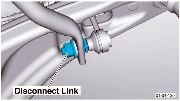
- Disconnect the lower suspension arms (Refer to 'Front Suspension (04.01)', page 4-2-1).
Disconnect the anti-roll bar from the lower arms. Leave the anti-roll bar attached to the subframe.
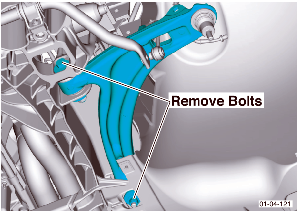
- Remove bolts (x2) that secure the engine mounts to the subframe.
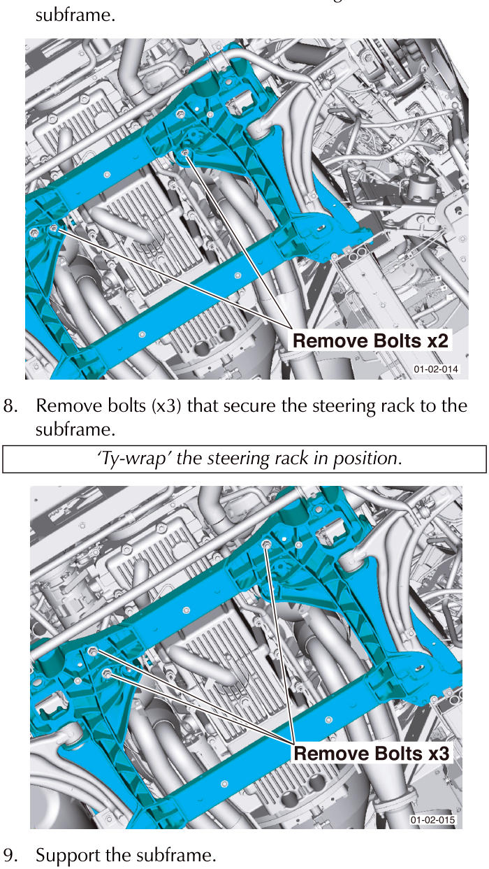
- Remove bolts (x3) that secure the steering rack to the subframe.
'Ty-wrap' the steering rack in position.
- Support the subframe.
- Ensure that the relation of the subframe to the front structure and the vehicle body is marked (scribed), for accurate installation.
Parts & tools for this job For 2005 Aston Martin DB9
Links open Amazon search results in a new tab. As an Amazon Associate I earn from qualifying purchases.