
Lubrication (page 2 of 2)
- Make
- Fiat
- Model
- Bravo /Brava (182) Factory Service Manual
- Year
- 1995–2001
- Section
- Engine
00 Introduction and technical dataLubrication · page 2 of 2
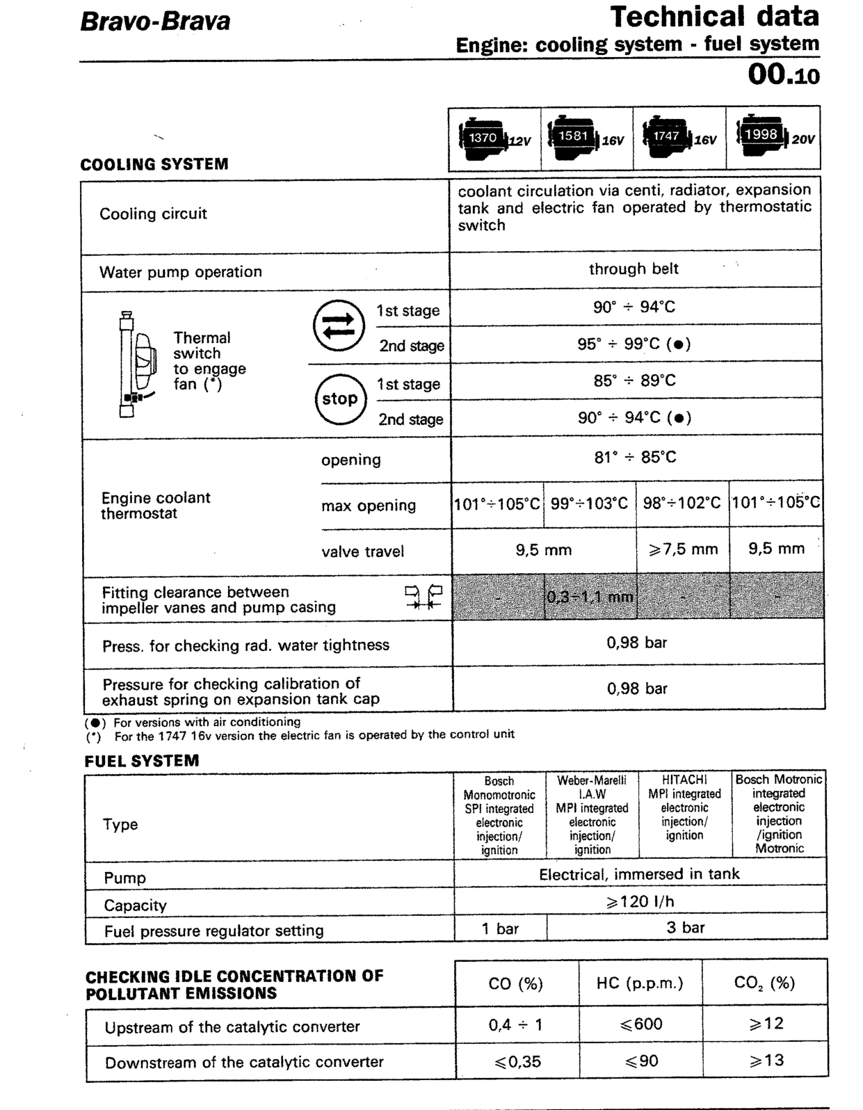
| F1 | 1370 12V | 1581 16V | 1747 16V | 1998 20V | |
|---|---|---|---|---|---|
| COOLING SYSTEM | |||||
| Cooling circuit | coolant circulation via centi, radiator, expansion tank and electric fan operated by thermostatic switch | ||||
| Water pump operation | through belt | ||||
Thermal switch to engage fan (*) |
1st stage |
90° ÷ 94°C | |||
| 95° ÷ 99°C (●) | |||||
1st stage |
85° ÷ 89°C | ||||
| 90° ÷ 94°C (●) | |||||
| Engine coolant thermostat |
opening | 81° ÷ 85°C | |||
| max opening | 101°÷105°C | 99°÷103°C | 98°÷102°C | 101°÷105°C | |
| valve travel | 9,5 mm | ≥7,5 mm | 9,5 mm | ||
| Fitting clearance between impeller vanes and pump casing |
- | 0,3÷1,1 mm | - | - | |
| Press. for checking rad. water tightness | 0,98 bar | ||||
| Pressure for checking calibration of exhaust spring on expansion tank cap |
0,98 bar | ||||
(●) For versions with air conditioning
(*) For the 1747 16v version the electric fan is operated by the control unit
| F2 | Bosch Monomotronic SPI integrated electronic injection/ignition | Weber-Marelli I.A.W MPI integrated electronic injection/ignition | HITACHI MPI integrated electronic injection/ignition | Bosch Motronic integrated electronic injection /ignition Motronic | |
|---|---|---|---|---|---|
| Type | |||||
| Pump | Electrical, immersed in tank | ||||
| Capacity | ≥120 l/h | ||||
| Fuel pressure regulator setting | 1 bar | 3 bar | |||
| CHECKING IDLE CONCENTRATION OF POLLUTANT EMISSIONS | CO (%) | HC (p.p.m.) | CO2 (%) |
|---|---|---|---|
| Upstream of the catalytic converter | 0,4 ÷ 1 | ≤600 | ≥12 |
| Downstream of the catalytic converter | ≤0,35 | ≤90 | ≥13 |
Original page
Parts & tools for this job For 1995 Fiat Bravo
- PARTOil filterSearch: Fiat Bravo 1995 oil filter
- TOOLOil filter wrenchSearch: oil filter wrench
- FLUIDEngine oilSearch: Fiat Bravo engine oil
Links open Amazon search results in a new tab. As an Amazon Associate I earn from qualifying purchases.